Installing the TUBING ASSEMBLY COVER
8B6658 – 29JUN96
5
Section 2: Installing the TUBING ASSEMBLY COVER
[1] See Step 13 on Page 4 to determine if Sections 2 and 3 must be done.
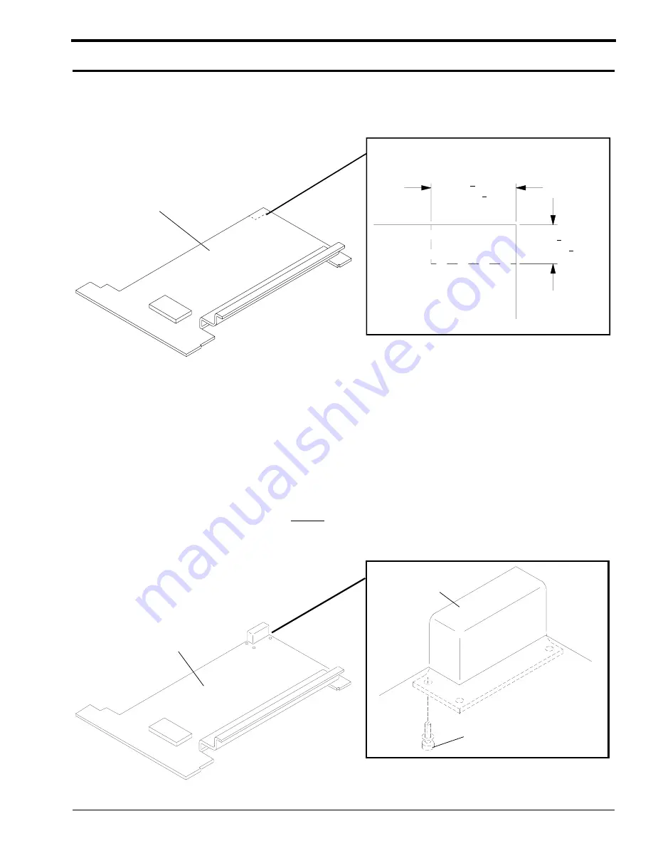
Figure 3
Cutting the WET SECTION COVER
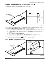
[2] Use the TIN SNIPS or the HACK SAW to cut the WET SECTION COVER as shown in Figure 3 above.
[3] Using the TUBING ASSEMBLY COVER as a template, do the following steps:
(a) Align the TUBING ASSEMBLY COVER with the WET SECTION COVER as shown in Figure 4 below.
(b) Check that the edge of the TUBING ASSEMBLY COVER is under the WET SECTION COVER. See
Figure 4.
(c) Use the CENTER PUNCH to mark the holes.
(d) Use the 3.2 mm (
1
⁄
8
in.) DRILL BIT and the ELECTRIC DRILL TL-1466 to drill the holes.
[4] Install the TUBING ASSEMBLY COVER by inserting the 3 FASTENERS up through the holes in the
TUBING ASSEMBLY COVER and the bottom of the WET SECTION COVER.
Figure 4
Installing the TUBING ASSEMBLY COVER
8.6 cm 3mm
(3 3/8 in. 1/8 in)
+
+
3.2 cm 3mm
(1 1/4 in. 1/8 in)
+
+
H104_0537BA
H104_0537BCA
COVER
WET SECTION
H127_0184BC
H127_0184BCA
FASTENER (3)
COVER
ASSEMBLY
TUBING
COVER
WET SECTION
Summary of Contents for 3059
Page 2: ......
Page 3: ......
Page 4: ......
Page 5: ......
Page 6: ......
Page 7: ......
Page 8: ......
Page 9: ......
Page 10: ......
Page 11: ......
Page 12: ......
Page 13: ......
Page 14: ......
Page 15: ......
Page 16: ......
Page 17: ......
Page 18: ......
Page 19: ......
Page 20: ......
Page 21: ......
Page 22: ......
Page 23: ......
Page 24: ......
Page 25: ......
Page 26: ......
Page 27: ......
Page 28: ......
Page 29: ......
Page 30: ......
Page 31: ......
Page 32: ......
Page 33: ......
Page 34: ......
Page 35: ......
Page 36: ......
Page 37: ......
Page 38: ......
Page 39: ......
Page 40: ......
Page 41: ......
Page 42: ......
Page 43: ......
Page 69: ...MODIFICATION INSTRUCTIONS TYPE1 10 29JUN96 8B6658 ...

