MODIFICATION INSTRUCTIONS, TYPE1
12
28JUL95 – 5B6773
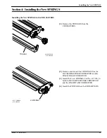
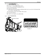
Installing the New SPRINGS in the WASH RACK
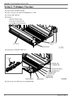
[5] Remove from both the LOWER and UPPER
IDLER GEARS on the WASH RACK:
• SHOULDER SCREW
• BUSHING
• IDLER GEAR
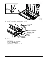
[6] Remove and discard the 6 SPRINGS from the
WASH RACK
a. To remove the top SPRING on the non-drive
side of the RACK, do the steps below.
1. Remove the SPRING from around the
BEARING.
2. Place the SPRING between the teeth of
the GEAR.
3. Rotate the GEAR.
[7] Install the 6 new SPRINGS, Part No. 1C7107.
[8] Install the:
• IDLER GEARS
• BUSHINGS
• SHOULDER SCREWS
Installing the New SPRINGS in the DRYER RACK
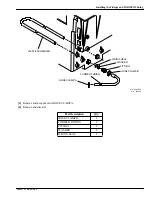
[9] Remove the following parts from the UPPER
SQUEEGEE ROLLER on the non-drive side of
the DRYER RACK:
• SPRING and discard
• E-RING and keep
[10] For access to the GEAR PIN, move the UPPER
SQUEEGEE ROLLER toward the drive side of
the PROCESSOR.
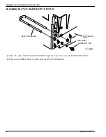
[11] Remove from the drive side of the UPPER
SQUEEGEE ROLLER:
• GEAR PIN
• SPROCKET
• WASHER
• SPRING and discard
[12] Reverse Steps 9 through 11 to install the 2 new
SPRINGS, Part No. 1C7106.
H127_0179AA
14 BEARINGS
H127_0179ACA
SCREW
SHOULDER
BUSHING
GEAR
LOWER IDLER
6 SPRINGS
UPPER IDLER
GEAR
H127_0201AA
ROLLER
LOWER SQUEEGEE
drive side
WASHER
SPROCKET
GEAR PIN
2 SPRINGS
ROLLER
UPPER SQUEEGEE
H127_0201ACA
Summary of Contents for 3059
Page 2: ......
Page 3: ......
Page 4: ......
Page 5: ......
Page 6: ......
Page 7: ......
Page 8: ......
Page 9: ......
Page 10: ......
Page 11: ......
Page 12: ......
Page 13: ......
Page 14: ......
Page 15: ......
Page 16: ......
Page 17: ......
Page 18: ......
Page 19: ......
Page 20: ......
Page 21: ......
Page 22: ......
Page 23: ......
Page 24: ......
Page 25: ......
Page 26: ......
Page 27: ......
Page 28: ......
Page 29: ......
Page 30: ......
Page 31: ......
Page 32: ......
Page 33: ......
Page 34: ......
Page 35: ......
Page 36: ......
Page 37: ......
Page 38: ......
Page 39: ......
Page 40: ......
Page 41: ......
Page 42: ......
Page 43: ......
Page 69: ...MODIFICATION INSTRUCTIONS TYPE1 10 29JUN96 8B6658 ...

