background image

12

CA280  M280EN1

1

1

2

1

2

Hydraulic reservoir
– Checking the fluid level

Refuel every day. Top off to the lower edge of the filler
pipe. Use diesel fuel in accordance with the engine
manufacturer’s specifications.

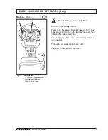
Stop the diesel engine. Short (press) the
filler gun against a non-insulated part of
the roller before refueling, and against the
filler pipe (1) while refueling is in progress.

The fuel tank holds 250 litres (66 gal).

EVERY 10 HOURS OF OPERATION (Daily)

Engine
– Checking the oil level

Fig. 7 Engine compartment

1. Oil dipstick

Place the roller on a level base. The engine
must be switched off and the parking brake
applied for all checking and adjustments
on the roller unless stated otherwise.

Observe caution. Beware of hot parts of
the engine and hot radiator when taking
out the oil dipstick. Wear gloves and safety
goggles.

The dipstick is on the right-hand side of the engine.

Pull the dipstick (1) up and check that the oil level is
between the upper and lower marks. See the engine
manual for further details.

Fig. 8 Fuel tank

1. Filler pipe
2. Fuel pre-filter

Fuel tank – Refueling

Check that there is no sediment or water in the
fuel pre-filter (2).
Clean the pre-filter if required, see under "500
hours of operation".

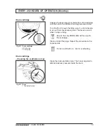
Fig. 9

Hydraulic  reservoir

1. Sight glass
2. Filler pipe

Place the roller on level ground and check that the fluid
level is between the max. and min. marks in the sight
glass (1). Top off with hydraulic fluid according to the
lubricant specification if the level is too low.

Summary of Contents for CA280

Page 1: ...DYNAPAC CA280 Box 504 SE 371 23 Karlskrona Sweden Phone 46 455 30 60 00 Fax 46 455 30 60 30 www dynapac com M280EN1 MAINTENANCE ...

Page 2: ...19 ILF015WO1 ...

Page 3: ...s Printed in Sweden K EEP TH IS M A N U A L FO R FU TU R E R EFER EN C E One of Dynapac s medium heavy vibratory soil compactors is the CA280 It is available in a solely wheel driven version and in a wheel and drum driven version called CA280D All types of base courses and reinforcement courses can be compacted to considerable depth The cab and safety related accessories are described in this manu...

Page 4: ...ic measures that should normally be performed by the operator The manufacturer s instructions noted in the engine manual also apply This is placed under a separate flap in the roller s product folder GENERAL Safety instructions Personal safety Special caution Machine or component damage WARNING SYMBOLS CALIFORNIA Proposition 65 Warning Diesel engine exhaust and some of its constituents are known t...

Page 5: ...ure Shell Spirax SAE 80W 90 HD API GL 5 15 C 40 C 5 F 104 F ambienttemperature Shell Spirax HD85W 140 or equivalent higher than 40 C above 104 F DRUM CARTRIDGE OIL Synthetic oil MOBIL SHC 629 GREASE SKF LGHB2 NLGI class 2 or equivalent for the articulation Shell Retinax LX2 or equivalent for other grease points FUEL See engine manual COOLANT GlycoShell or equivalent 50 50 mixture with water Anti f...

Page 6: ... each side Hydraulic reservoir 52 13 7 gal Fluid in hydraulic system 23 6 gal Lubricating oil Diesel engine 10 10 6 qts Coolant Diesel engine 18 4 8 gal Fuel tank 250 66 gal Electrical system Battery 12 V 170 Ah Alternator 14 V 63A Fuses See under main heading Electrical system Tires Tire size 23 1 x 26 0 8 Ply 600 60 30 5 Air pressure 110 kPa 1 1 kp cm2 As extra equipment the tires can be filled ...

Page 7: ... 7 34 21 1 M10 40 15 5 56 41 3 68 25 1 M12 70 51 6 98 72 3 117 86 3 M16 169 124 7 240 177 290 213 9 M20 330 243 4 470 346 7 560 413 1 M24 570 420 4 800 590 1 960 708 1 M30 1130 833 5 1580 1165 4 1900 1401 4 M36 1960 1445 7 2800 2065 3 Tightening torque in Nm lbf ft for oiled bright galvanized bolts tightened with a torque wrench Bolt size M24 P N 90 39 64 Strength class 10 9 Tighteningtorque 800 N...

Page 8: ... vary when driving on different courses and with different seat positions The vibration values are measured in conformance with the operation cycle described in EU directive 2000 14 EC on EU equipped machines on soft polymer material with vibration switched ON and operator s seat in the transport mode Operator s station vibration hand arm steering wheel lever Below limit value Limit value 2 5 m s2...

Page 9: ...use box 11 Drum cartridge oil filler x2 12 Drum gearbox 13 Scrapers 14 Drum cartridge oil level plug x2 15 Rubber elements and fastening screws 16 Steering joint 17 Steering cylinder x2 18 Flywheel casing hydraulic pumps 19 Wheel nuts 20 Tire pressure 21 Rear axle differential 22 Rear axle planetary gearing x2 23 Rear axle suspension two sides 24 Oil filter diesel engine 25 Draining fuel tank 26 E...

Page 10: ...r 11 30 Check coolant level 11 Seeengineinstructionmanual 2 Check oil level in the engine 12 Seeengineinstructionmanual 28 Refuel 12 5 Check the hydraulic reservoir level 12 Test the brakes 13 Every 10 hours of operation daily Items in Measure See page Comments fig 1 4 Check that hoses and connections are tight 14 6 Control clean the filter element in the air cleaner 14 Replace as required 16 Grea...

Page 11: ...in filter in the air cleaner 24 21 Change oil in the rear axle differential 25 22 Change oil in the rear axle planetary gearing 26 Check engine valve clearance Seeengineinstructionmanual 32 Check belt tension of drive system Seeengineinstructionmanual Every 1000 hours of operation every six months Itemsin Measure See page Comments fig 1 8 9 Change the hydraulic fluid 27 12 Change oil in the drum c...

Page 12: ...nts are made closer than the values noted below the scrapers may be damaged or the drum may wear more than usual v If required adjust distance to the drum as follows Loosen the screws 2 and adjust to 20 mm 0 8 in Tighten the screws Scrapers Checking Adjusting Fig 2 Scrapers 1 Scraper blade 2 Screws x4 Fig 3 Scrapers 1 Scraper blade 2 Screws CA280 Double steel scrapers Optional Loosen the screws 2 ...

Page 13: ...3 Filler cap Ensure that coolant level is between the max min marks The coolant tank is located above the engine cooling fan and is best visible from the left side of the roller The filler cap 3 is accessible from the top of the engine hood see figure above Fill with coolant consisting of 50 water and 50 antifreeze See page 3 in these instructions and the enginemanual Change the coolant and flush ...

Page 14: ... and adjustments on the roller unless stated otherwise Observe caution Beware of hot parts of the engine and hot radiator when taking out the oil dipstick Wear gloves and safety goggles The dipstick is on the right hand side of the engine Pull the dipstick 1 up and check that the oil level is between the upper and lower marks See the engine manual for further details Fig 8 Fuel tank 1 Filler pipe ...

Page 15: ...arning lamp Check brake operation as follows Drive the roller slowly forward Press down the reserve parking brake knob 1 The brake warning lamp 3 on the instrument panel should light and the roller should stop After testing the brakes set the forward reverse lever 2 in neutral Pull out the reserve parking brake knob The roller is now ready for operation ...

Page 16: ...er with a new one after every fifth replacement or cleaning of the main filter The secondary filter cannot be cleaned To change the backup filter 4 pull the old filter out of its holder insert a new one and reassemble the air cleaner in the reverse order in relation to the instructions in the figure above Fig 13 Air filter 4 Backup filter Backup filter Replacement To clean the main filter blow up ...

Page 17: ...bricant nipple right rear steering cylinder mount x1 4 Lubricant nipple left rear steering cylinder mount x1 Fig 15 Steering joint right side 1 Grease nipples steering joint x4 2 Grease nipple cylinder mount x1 EVERY 50 HOURS OF OPERATION Weekly Wipe the nipples clean from grease and dirt Grease the nipples 3 and 4 with five strokes of the grease gun Turn the steering wheel fully to the right to g...

Page 18: ... tions Check both tires When you change the tires it is important that both tires have the same rolling radius to ensure proper operation of the anti slip device in the rear axle Check tightening torque of the wheel nuts 2 at 470 Nm 350 lbf ft Check both wheels and all nuts Applies only on new machine or newly fitted wheels When pumping the tires see the safety manual that accompanies the roller N...

Page 19: ...ne running Park on a level surface Block the wheels securely Wipe clean remove the level plug 1 and check that the oil level reaches the lower edge of the plug hole Top off to the right level if the level is low Use trans mission oil See lubricant specification Position the roller with the plug 1 in the planetary gearing at 9 o clock Wipe clean remove the level plug and check that the oil level re...

Page 20: ...m cartridge Checking the oil level Wipe the filling plug and level plug clean from dirt Unscrew the filling plug 1 Fig 21 Level check drum gearbox 1 Level plug 2 Filler plug 3 Drain plug Drum gearbox Checking the oil level Position the roller with the filler plugs 2 straight up Wipe clean round the level plug 1 and unscrew it Ensure that the oil level reaches up to the lower edge of the plug hole ...

Page 21: ...at the bottom of the cartridge until the hole in the middle of the plug becomes visible Top off with oil through the filling plug 1 until oil begins to run out from the level plug hole The level is correct when it stops running Ensure that only MOBIL SHC 629 is used in the cartridges Clean and refit the plugs Repeat the procedure on the opposite side Do not overfill with oil risk for overheating D...

Page 22: ...coolers 1 2 and 3 is unobstructed Clean a dirty radiator using compressed air or a high pressure water jet Blow or wash the radiator in the opposite direction to that of the cooling air Take care when using a high pressure water jet do not hold the nozzle too near the cooler The cooler may otherwise be damaged Wear protective goggles when working with compressed air or high pressure water jet Cool...

Page 23: ...en connecting the battery always connect the positive cable first Discard used batteries in a proper way Batteries contains lead which is detrimental to the environment Before doing any electric welding on the machine disconnect the battery ground cable and then all electrical connections to the alternator Battery cell Fig 30 Electrolyte level in battery 1 Cell cap 2 Electrolyte level 3 Plate EVER...

Page 24: ...re there is adequate ventilation extraction if the diesel engine is run in doors Risk of carbon monoxide poisoning Fig 32 Left side of engine 1 Drain plug 2 Oil filter Diesel engine Oil and filter change Place the roller on a level surface Switch off the engine and apply the parking brake Reserve brake The oil drain plug 1 is most easily accessible from underneath the engine Drain off the oil whil...

Page 25: ... type and cannot be cleaned Ensure that the old sealing ring is not left on the filter holder Leakage may otherwise occur between the new and the old seals Thoroughly clean the sealing surface of the filter holder Apply a thin coat of fresh hydraulic fluid on the new filter seal Screw on the filter by hand First screw on until the filter seal lies against the filter holder Then screw a further hal...

Page 26: ...ows from the plug Tighten the plug again EVERY 1000 HOURS OF OPERATION Every six months Fig 36 Fuel tank 1 Drain plug Fuel tank Draining Replace the main filter of the air cleaner even if it has not yet been cleaned five times see every 50 hours of operation for changing the filter Fig 37 Air cleaner 1 Locking flaps 2 Cover 3 Main filter 4 Backup filter 5 Filter housing Air filter Changing Hydraul...

Page 27: ...an and remove the level filler plug 1 and all five drain plugs 2 and drain the oil into a suitable receptacle The volume is almost 12 litres 12 7 qts Save the oil and deposit it in an approved manner Refit the drainage plugs and top up with fresh oil until the correct level is reached Note It takes a while for the oil to flow into the axle Do not fill the entire volume all at once Refit the oil le...

Page 28: ...ith the plug 1 at its lowest position Wipe clean unscrew the plug 1 and drain the oil into a suitable receptacle The volume is about 2 litres 2 1 qts Save the oil and deposit it in an approved manner Position the roller with the plug at 9 o clock Fill with oil to lower edge of level hole Clean and screw the plug back into place and repeat the procedure on the other side Use transmission oil See lu...

Page 29: ...er unless otherwise specified Observe caution when draining hot oil Protect your hands Obtain a container for collecting the used fluid The con tainer should have a volume of at least 60 litres 16 gal A suitable container may be an empty oil drum or similar item which is placed beside the roller The fluid then runs in a hose from the drainage plug 1 to the oil drum after the plug 2 has been remove...

Page 30: ...evel plug 3 according to Drum gearbox Checking the oil level Use transmission oil see Lubricant Specification Clean and refit the level plug 3 and filler plug 2 Steering joint Check Inspect the steering joint to detect any damage or cracks Check and correct any loose bolts Check also for any stiffness and play Fig 45 Steeringjoint Fig 46 Operator s station 1 Forward Reverse lever 2 Screws Controls...

Page 31: ...e Grease the steering cylinder s piston with conservation grease Grease also the engine compartment cover s hin ges the seat slide rails the engine speed control and the forward reverse control mechanism Ensure that tire pressure is 110 kPa 1 1 kp cm2 Place the instrument cover on the steering column Cover the entire machine with a tarpaulin which should hand some way off the ground If possible st...

Page 32: ...rotective cab never subject the structure or cab to welding or drilling Never attempt to repair a damaged structure or cab they must be replaced with new ones When using an auxiliary battery to assist starting always connect the positive terminal of the auxiliary battery to the positive terminal of the roller battery and negative to negative Starting aid Protective structure ROPS Fire fighting Hig...

Page 33: ...ity to ground The cable between battery and alternator must not be disconnected when the engine is running Fig 48 Instrument panel 1 Screws 2 Screws Fuses and relays Fig 49 Instrument panel 3 4 Fuse box 5 VBS relay 6 Main relay 7 Hourmeter relay 8 Lights relay Optional Fuse boxes in steering column Fig 50 Fuse box left side 7 5A 1 Hourmeter 7 5A 2 VBS relay 7 5A 3 Warning lamp 7 5A 4 Horn Fuel gau...

Page 34: ...screws to release the plastic cover The fuses are of the flat pin type The fuel solenoid relay 2 and the start relay 3 are also located here Main fuse 30 A Green Fig 52 Relay box viewed from the rear Cummins stage 2 engine 2 Preheating relays 3 Start relay 4 Main fuse 5 Control box for engine preheater Applies to Cummins stage 2 engine only There is one main fuse 1 located behind the battery disco...

Page 35: ......

Reviews: