background image


1-8 

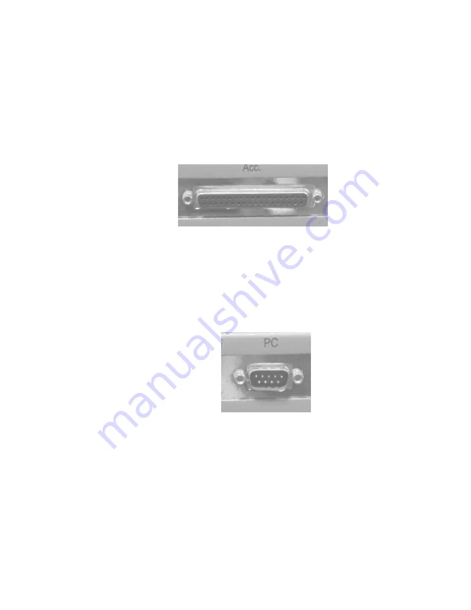
1.10 Connecting Accessory to DB-20 

The Acc port is for the connection and control of a variety of optional 
accessories available from Dynamica such as Auto Sipper, Electronic 
Thermostatic cell holder.  Connect the optional accessories using the cable 
provided along with the optional accessories.  Please refer to the installation 
manual for detail for installation of optional accessories. 


1.11 Connecting DB-20 to PC Software 

Optional PC software allows DB-20 to be fully controlled by the software and 
perform data analysis using the PC software.  Connect the serial cable provided 
with PC software to the port marked PC.  Please also set the Local-Remote 
switch to Remote when using PC software. 


1.12 Connecting USB Flash Memory  

DB-20 is equipped with a USB port to connect commercial available USB flash 
memory for the storage of data generated by the DB-20.  The data generated in 
the DB-20 can save into USB flash memory with File Manager of DB-20.  Refer 
to the relevant chapter for operation.  The data can be transferred to standard 
computer for storage also.  Simply insert the USB flash memory disk into the 
port.  USB flash memory of Kinston Data Traveller ( Compatible to USB

1.1 and 

FAT file system 

) is tested to be compatible.  Contact your Dynamica sales agent 

to obtain the latest list of the compatible Flash Memory.  

Summary of Contents for HALO DB-20

Page 1: ... 20 Spectrophotometer Instruction Manual Please read through this manual carefully and store it in a safe place Before using the instrument please read the safety instructions and precautions carefully Keep this manual in a safe place nearby to access ...

Page 2: ...AL HALO DB 20 UV Vis Spectrophotometer Read and keep this manual Read the safety instructions carefully and understand them before using the equipment Keep this manual at hand for reference Dynamica Ltd Version No V1 1 ...

Page 3: ...als and Samples IMPORTANT 5 2 Notice on Instruction Manuals IMPORTANT 5 3 Trademark Acknowledgments IMPORTANT 5 SAFETY SUMMARY SAFETY 1 THE PERSONAL COMPUTER SAFETY 10 COMPUTER VIRUSES AND BACKUP DATA SAFETY 10 WARNING DISPLAY LABELS SAFETY 11 CHAPTER 1 INSTALLATION 1 1 1 1 UNPACKING 1 1 1 2 INSTALLATION SITE 1 2 1 2 1 Installation Conditions 1 2 1 2 2 Installation Environment 1 2 1 3 CHECK OF CON...

Page 4: ...h Scan 2 5 2 4 3 Time Scan 2 6 2 4 4 Secondary Processing Functions 2 6 2 4 5 Data Storage Function 2 7 2 4 6 Automatic Start Function 2 8 2 4 7 Automatic Calibration and Self Diagnosis Functions 2 8 2 5 SPECIFICATION 2 8 CHAPTER 3 OPERATIONAL METHOD 3 1 3 1 BASIC OPERATION 3 1 3 1 1 Operational Procedure 3 1 3 1 2 Key Panel Functions 3 1 3 2 PRELIMINARY OPERATION 3 3 3 2 1 Initialization 3 3 3 2 ...

Page 5: ... 3 8 2 Set Time 3 59 3 8 3 Recording Lamp Usage 3 60 3 8 4 GLP GMP 3 60 3 9 TEST MENU 3 65 3 9 1 Retrieving a Test Stored in Inside Memory 3 65 3 9 2 Deleting Test From Inside Memory 3 65 3 9 3 Autostart Function 3 66 CHAPTER 4 MAINTENANCE 4 1 4 1 SELF DIAGNOSIS AND AUTOMATIC ADJUSTMENT 4 1 4 2 CONFIRMATION OF SPECIFICATIONS 4 1 4 2 1 Wavelength Accuracy 4 1 4 2 2 Spectrum Bandwidth 4 2 4 2 3 Chec...

Page 6: ...5 2 PARTS REPLACEMENT 5 1 5 2 1 Replacement of Light Source Lamp 5 1 5 2 2 Change Source Lamp Usage Time 5 4 Notice A IV ...

Page 7: ...r samples would result not only in wrong analytical data but in consequences adverse to safety Before using the instrument be sure to read through this instruction manual to enable correct use For installation maintenance of the instrument read the instruction manual carefully to attain a full understanding of the instructions Be sure to observe cautionary instructions Keep this manual handy for e...

Page 8: ...Increase separation between the instrument and radio TV receiver Connect the instrument to an outlet on a circuit different from that to which the radio TV receiver is connected 2 Possible Electromagnetic Wave Interference Affecting This Instrument If this instrument is used near an intense electromagnetic source interference noise may be given to the instrument to incur an adverse effect on its p...

Page 9: ...e instruction manual provided it is used in accordance with the instructions described in the manual 1 Scope of Warranty a Any parts which prove to be defective in design or workmanship during the warranty period will be repaired without charge b A substitute part may be used for repair or replacement with an equivalent product may be made instead of repair c Such system components as a personal c...

Page 10: ...ardware software or spare parts other than supplied by us f Failure due to improper handling or maintenance by the user g Failure due to maintenance or repair by a service agent not approved or authorized by us h After disposal of this instrument or after its resale without our approval i Failure due to relocation or transport after initial installation j Failure due to disassembly modification or...

Page 11: ...ranty Any other implied warranties of merchantability and fitness for a particular purpose are not included in this warranty No liability is assumed for direct or indirect damages arising out of explicit or implied warranties b Oral or written information or advice given by our dealers distributors agents or employees without our express permission shall not create a warranty or in any way increas...

Page 12: ...rded as instructed by the respective suppliers 2 Notice on Instruction Manuals 1 Information contained in the instruction manuals furnished with the instrument is subjected to change without notice for product improvement 2 This manual is copyrighted by Dynamica with all rights reserved 3 No part of this manual may be reproduced or transmitted in any form or by any means without our express writte...

Page 13: ...azard warnings which appear on the warning labels on the product or in the manual have one of the following alert headings consisting of an alert symbol and a signal word DANGER WARNING or CAUTION DANGER Indicates an imminently hazardous situation that if not avoided will result in death or serious injury It does not apply to this equipment WARNING Indicates a potentially hazardous situation that ...

Page 14: ...d to the safety of a person SAFETY 2 Attention It is used to present warnings which are not directly related to personal injury hazards It is used to indicate prevention against damage to the equipment Note This is used to indicate instructions that enable you to operate the equipment accurately and perform accurate measurements ...

Page 15: ...ot follow the instructions in this manual an inaccurate analysis may result or bodily injury may occur Because of danger please make sure not to modify or alter the product make sure not to use unspecified parts and make sure not to operate the equipment by removing defeating the safety device s When using chemicals please make sure to ventilate the room well If there is not enough ventilation it ...

Page 16: ... Installation of this instrument shall be carried out by or under supervisions of qualified service personnel of Dynamica or its authorized service agent When relocation of this instrument becomes necessary after initial installation delivery please notify your local Dynamica sales representative or nearest Dynamica service office Technical support service for this instrument is available from s s...

Page 17: ... your health WARNING Eye Injury from Organic Solvents Handling Organic Solvents Please wear protective glasses when using organic solvents If the organic solvent should get into your eye flush your eye immediately under running water for at least 5 minutes while keeping your eyelids open See a physician for appropriate treatment SAFETY 5 ...

Page 18: ...G Electrical Shock Electrical Shock from Contact High voltage is used inside of the equipment Never remove the cover except by a service person or as instructed in the section for lamp replacement When cleaning the inside of the cell compartment be sure to turn off the unit CAUTION High Temperature Burns from high temperatures The lamp will become very hot during operation please make sure that th...

Page 19: ...hair caught Please assure your safety before operation CAUTION Fatigue due to Prolonged Work Data Processing Viewing the display in your work can cause eye and physical fatigue if you continue to work in the same posture for extended periods When working with the display for a prolonged period for your health make sure to take breaks for 10 to 15 minutes every hour in order to rest your eyes and b...

Page 20: ...cautions regarding Accuracy and Precision of Measurements Do a routine check prior to taking measurements In order to obtain accurate measuring results please perform tests as instructed following the instructions in Chapter 3 SAFETY 8 ...

Page 21: ...ess than 10 Ω Defective grounding may not only cause lower resistance against noise from the outside but it can also cause the Mass Spectrometer and personal computer to generate static electricity which may involve the danger of electrical shocks A high voltage circuit is used inside the UV Vis Spectrophotometer Do not open the covers when this circuit is operational because of the danger from el...

Page 22: ... is encountered the personal computer may be infected by a computer virus Computer viruses are malicious programs that sneak into the personal computer to cause misbehavior or damage to data A program designed to offer protection against computer viruses is called a vaccine program virus scan Do not use any programs or storage media that are suspected of containing a virus If there is a possibilit...

Page 23: ...r High temperature can cause burns Light source lamp and lamp chamber remain hot for a while even after Power off Before lamp replacement turn power off and wait at least 20 minutes 134 1973 High voltage 500V Can cause fatal or serious injury Before removing light source cover turn power switch off Never release safety mechanism inadvertently ...

Page 24: ...on should be paid when taking it out Fig 1 1 HALO DB 20 Spectrophotometer Note The light source switching mirror is secured with the sponge rubber material for transport at shipment from the factory After using open the light source cover and remove the protective sponge from the light source switching mirror The shipping crate cannot be claimed for compensation even if it is damaged during the tr...

Page 25: ...tains on coming off please notify local Dynamica sales representative or service office New labels will be provided Grounding line Grounding line resistance of 100Ω or less is required Place for Installation Minimum floor area Floor area with a width of 550 mm and a depth of 710 mm or more is required Floor strength Floor strength 30kg or more Select a rigid and horizontal plane capable of withsta...

Page 26: ...nt the mainframe cover being heated beyond 70 Avoid the vicinity of instruments that generate a strong electric field such as an electric welding machine high frequency furnace or pole transformer Avoid a dusty environment otherwise optical performance might deteriorate The line voltage must be stable and free from a rapid fluctuation otherwise noise might increase Do not turn on and off frequentl...

Page 27: ...ies are subject to change for improvement without previous notice Check them for proper quantity against the packing list furnished with the instrument 1 4 Check of Voltage and Fuse Please first check if the line voltage is suitable for the line voltage allowed using labeled beside the power connector Warning Before proceeding to the work make sure the power cord is not connected to the wall socke...

Page 28: ...itch Printer port LCD brightness adjustment port Local Remote switch for PC software control or Local keypad control Acc Port for connection of accessories such as auto sipper 9 pin Serial port for connection to personal computer 1 6 Connection of Power Cord and Grounding Wire Note Before plugging in the power cord be sure to turn off the POWER switch and be sure to select proper power cord The ca...

Page 29: ...er of table tap be sure its grounding wire to the grounding terminal securely Fig 1 4 How to Ground the HALO DB 20 1 7 Connection of Printer Connect the printer with the instrument if to use the printer with a standard parallel printer cable The connector of printer is on the right side of the ...

Page 30: ...se refer to the relevant instruction manual of printer to install the printer 1 8 Local Remote switch DB 20 can be controlled by the optional PC software or simply via keypad control Please put the Local Remote switch to Local when using keypad and LCD on the DB 20 When connecting to the PC software switch the Local Remote switch to Remote position The LCD will display PC Control when connected to...

Page 31: ...the serial cable provided with PC software to the port marked PC Please also set the Local Remote switch to Remote when using PC software 1 12 Connecting USB Flash Memory DB 20 is equipped with a USB port to connect commercial available USB flash memory for the storage of data generated by the DB 20 The data generated in the DB 20 can save into USB flash memory with File Manager of DB 20 Refer to ...

Page 32: ...1 9 ...

Page 33: ...intensity It of monochromatic radiation the following equation 1 can be set up It I0 10 ε c l τ 1 Where ε is a constant known as absorptivity which varies depending on the sample Equation 1 represents the statement of Lambert Beer law and τ indicates transmittance which is often expressed as a percentage i e τ 100 T percent transmittance or T Also the common logarithm of inverse transmittance can ...

Page 34: ... system of the HALO DB 20 Sample Compartment Monochromator Detector 1 Lens Sample Beam Grating Enter Slit Mirror M1 WI lamp D2 lamp Filter F Exit Slit Half Mirror HM Mirror M3 Mirror M4 Detector 2 Mirror M2 Reference Beam Lens Fig 2 2 Optical System of HALO DB 20 Spectrophotometer ...

Page 35: ...cave diffraction grating realizes a monochromator featuring high energy efficiency and low stray light level The beam is separated by using a half mirror rather than a rotary mirror like in the conventional double beam spectrophotometer This structure serves to eliminate the moving parts thus realizing a highly stable and reliable monochromator The optical systems on the sample and reference beam ...

Page 36: ...bon tetrachloride 275 nm 400 nm Benzene 280 nm 400 nm Methyl ethyl ketone 335 nm 400 nm Acetone 340 nm 400 nm Carbon disulfide 380 nm 400 nm 2 3 2 Special Samples Note that the laws expressed by Equations 1 and 2 are not applicable to the following special samples Fluorescing sample Appreciably turbid sample In measurement of a solid sample as glass plate the energy of beam radiation undergoes a l...

Page 37: ...ue at a desired point can be read by moving the cursor to that point f Analytical results are displayed on the LCD together with the working curve Thus the results can be confirmed while observing the working curve g Working curve can be graphically plotted on the printer h Working curve can be generated by entering factor values i It is possible to generate a working curve by 2 3 wavelength measu...

Page 38: ...d variously to the stored data Automatic Data Readout A cursor can be moved to a desired point in the spectrum currently displayed on the LCD screen and a reading of the absorbance transmittance at that point Peak Detection Cursor can be moved to a peak position to display absorbance transmittance readings at the peak In addition an automatic peak selection routine allows peak and valley measureme...

Page 39: ...on multiplication or division between two spectra or calculate a constant value with the resulting data displayed on the LCD Recalculation During Rate Assay Kinetics Upon completion of a rate assay in the Time Scan mode you can adjust the calculation start time and end time to allow recalculation of the data 2 4 5 Data Storage Function The following data are stored in the memory and are not delete...

Page 40: ...e instrument and then press the START key The rest is done automatically 2 4 7 Automatic Calibration and Self Diagnosis Functions a Memory RAM and EPROM check b Wavelength drive mechanism check c Lamp ignition check d Automatic wavelength calibration Wavelength is automatically calibrated with reference to that of the beam emitted from the D2 lamp e Baseline Correction 2 5 Specifications 2 8 ...

Page 41: ...0 2 0Abs 0 3 T Photometry Reproducibility Measured with NIST 930D 0 001Abs 0 0 5Abs 0 002Abs 0 5 1 0Abs 0 004Abs 1 0 2 0Abs 0 15 T Baseline Flatness 0 002Abs 200 to 950 nm Baseline Stability 0 0003Abs h at 500 nm 2 hours after power up Noise Level 0 0003Abs 300s 500nm Wavelength Scan Speed 10 100 200 400 800 1200 2400 3600nm min Light Sources WI lamp D2 lamp Light Source Switchover Automatic chang...

Page 42: ...elow shows the operation panel of the HALO DB 20 There three groups to touch keys on the panel Special function Numerical Control Key Functions The function of each key on the HALO DB 20 key panel is described below Main Menu List the six data processing functions and retrieves the initial main menu frame Clear Return This key acts as a backspace key to erase the last character entered or acts as ...

Page 43: ... Zero Automatic zero adjustment In subsequent measurements each photometric value is determined with reference to the value stored above Start Stop Start or stop the measurement Print Data Used to copy data or spectrum from the screen to the printer Shift Upper When hold down this key allows you to use the keyboard keys to enter the upper alphabetical characters Shift Down When hold down this key ...

Page 44: ...m is checked the message OK will display if the item s function is normal or the message NG will display if the item s function is abnormal CONSULT THE TROUBLESHOOTING SECTION IF YOU FIND ERROR MESSAGE DURING INITIALIZATION Error Message 1 If the wavelength driver is NG the system will freeze And you must power off the instrument to solve the problem 2 If the other items are error the instrument c...

Page 45: ...ch procedure there is a prompt displayed at the bottom of each screen page The function of each option item refers to chapter 2 05 11 02 11 35 600 0 nm 0 854 ABS Main Menu 1 Photometry 2 Wavelength Scan 3 Time Scan 4 Multiple WL 5 File Manager 6 Calibration 7 Test Menu Select Function _ Selecting Options from the Main Menu You can access a desired option in one of two ways 1 The numeric key as the...

Page 46: ...ons and Variables Sub menu Option Variables Range Description of Function Parameter Setup Data Mode WL T ABS Conc 190 1100nm Measures transmittance absorbance and concentration Wavelength for analysis Sample Setup Name 02 11 02 Path Length Unit Label 1 9 A Z space Not more than 8 character 10mm Not more than 6 character Sample title Specify the concentration units Curve Setup Curve Type Curve Data...

Page 47: ...ell with lid Don t measure the combustible liquid or gas with this instrument If the sample is spilled over from the sample cell please blot up immediately with proper paper or cloth lest eroding the instrument Cautions 3 3 1 Step by Step Operation 3 3 1 1 Parameter Setup Press 1 to select Parameter Setup from the photometry submenu the parameter submenu list appears on the right side of the scree...

Page 48: ... the prompts 3 3 1 2 Sample Setup Press 2 to select Parameter Setup from the photometry submenu a submenu list appears on the right side of the screen as shown in the illustration below 11 02 02 11 35 600 0 nm 0 854 ABS Photometry 1 Parameter Setup 1 Name SAMP 1 2 Sample Setup 2 Path Length nm 10 0 3 Curve Setup 3 Unit Label MG L 4 Print Setup 5 System Setup 6 Save Parameter 0 Forward Select Funct...

Page 49: ...ameter 6 LO Limit 0 7 Forward Select Function _ Curve Type Note Function 2 to function 6 can only work at the Conc data mode Curve Type Press 1 on the keyboard The following four types of curves selectable are shown in the illustration below 11 11 02 11 35 600 0 nm 0 854 ABS Photometry 1 Parameter Setup 1 1st order 2 Sample Setup 2 STD NUM 3 Curve Setup 3 Curve Data 10 4 Print Setup 4 Repeat NUM 1...

Page 50: ...ed the numbers to fit the curve type Curve Data Input the standards concentration Press 3 key on the keypad to input the Curve Data The data list will appear on the right side of the screen as follows Left and right arrow key are used to select the ID of Standards STDs 11 11 02 11 35 600 0 nm 0 854 ABS Photometry 1 Parameter Setup STD Conc 2 Sample Setup 1 10 3 Curve Setup 2 20 4 Print Setup 3 30 ...

Page 51: ...s on the right side of the screen as shown in the illustration below 12 11 02 11 35 600 0 nm 0 854 ABS Photometry 1 Parameter Setup 1 ESC P 2 Sample Setup 3 Curve Setup 4 Print Setup 5 System Setup 6 Save Parameter 0 Forward Select Function _ Printer Type 1 ESC P 2 DPU 3 PCL3 Press the number key on the keyboard to select corresponding function DB 20 support three types printer namely EPSON series...

Page 52: ...Only Using D2 lamp over the entire wavelength region WI Lamp Only Using WI lamp over the entire wavelength region Lamp Change WL nm This parameter is used for selection of light source switching wavelength This spectrophotometer is provided with WI lamp for visible range measurement and D2 lamp for ultraviolet range measurement The wavelength is selectable with a range of 325 0 370 0 nm in increme...

Page 53: ...e following message appears Overwrite this File To delete the previous test variables and store the new variable set press ENTER To leave the old variables set intact and store new variables in a different location press RETURN 3 3 2 Performing Photometric Measurements Once the appropriate operating conditions are selected the system is ready for measurement 1 T or ABS selected for Data Mode Press...

Page 54: ...ear on the screen Data Save Yes Clear key No Enter key To save the measurement press Clear Return key and return the last display Then select the memory where you want to save the file Inside memory or USB If you do not want to save the measurement result press Enter key directly 2 Conc selected for Data Mode Select Conc data mode from item Parameter Setup After parameter being set up press 0 on t...

Page 55: ...ecified number of standards Upon completion of standard sample measurements a calibration curve is disp on the right side of the screen on which is shown in the illustration below s a calibration curve is disp on the right side of the screen on which is shown in the illustration below layed layed 1 Measure 2 Save Inside 3 Save to USB 4 Graph 5 Blank 6 Statistic 12 11 02 13 35 600 0 nm 0 854 ABS Ph...

Page 56: ...STD ABS Conc 1 1 0 068 1 2 0 068 1 0 068 0 000 ABS 2 1 0 098 2 2 0 100 0 050 2 0 099 0 068 0 000 MG L 0 200 Conc f ABS K0 0 000 K1 0 577 R 1 000 R2 1 000 Select Function _ 1 Measure 2 Save Inside 3 Save to USB 4 Graph 5 Blank 6 Statistic A 1 key on the keypad to measure the unknown sample Press 2 to save the measurement results The instrument can save 10 files 1 10 at most If you want to save the ...

Page 57: ...S K0 0 000 K1 0 577 R 1 000 R2 1 000 Select Function _ wavelength will be displayed at the bottom of the screen by pressing the left a right arrow key The display screen is shown as follow 11 12 02 14 28 600 0 nm 0 854 ABS Photometry 0 410 ABS 0 068 0 0 200 Conc f ABS K0 0 000 K1 0 577 R 1 000 R2 1 000 Select Function _ Trace conc 0 0 ABS 0 068 keypad to adjust the graph by changing the value of t...

Page 58: ... Then select Remeasure by pressing 1 on the keypad to remeasure the absorbance of this standard sample Select the Delete to delete the result you don t want 1 Remeasure 2 Delete 11 12 02 15 41 600 0 nm 0 854 ABS Photometry STD ABS Conc 1 0 068 0 0 2 0 098 1 0 3 1 025 5 0 1 1 0 068 2 2 0 068 Select Function _ If you need measure blank sample value press 5 before measure sample Once you press 5 key ...

Page 59: ...are calculated according the following is performed automatically and the measured results will be displayed on the LCD The measurement result will be displayed on the screen as follow Note Press Autozero key to exert an autozero before measurement statistics The display will be as following 13 11 02 15 55 600 0 nm 0 854 ABS Photometry 0 098 ID ABS Conc 1 0 087 5 0 2 0 098 10 0 0 087 0 MG L 10 0 S...

Page 60: ...ntration value of No i the number of samples ion sults are less than 2 the statistic function will not work Xi Th N MEAN the mean value SD Standard deviation CV Coefficient of variat Note If the measurement re 3 19 ...

Page 61: ...can 1 Parameter Setup 2 Sample Setup 3 Print Setup 4 System Setup 5 Save Parameter 6 User Baseline 0 Forward Select Function _ 3 4 1 Measurement Parameter Setting When the sample is volatile liquid please must cover the sample cell with lid Don t measure the combustible liquid or gas with this instrument Note 1 Parameter Setup Press 1 to select parameter setup from the Wavelength Scan Sub Menu and...

Page 62: ...n the sample side measurement d E R Energy on the reference side Start WL nm Start Wavelength for wavelength scanning operation Enter a long wavelength value of the measurement wavelength range This parameter is specifiable within a range of 190 to 1100 nm in increments of 0 1 nm Stop WL nm Stop Wavelength for wavelength scanning operation Enter a short wavelength value of the measurement waveleng...

Page 63: ... ABS Within a range of 3 000 to 3 000 in increments of 0 001 T Within a range of 0 to 600 0in increments of 0 1 Lower limit on Y axis The specifiable range fo ABS Within a range of 3 000 to 3 000 in increments of 0 001 T Within a range of 0 to 600 0 in increments of 0 1 Wavelength scannin The following eight speed val 1 10 2 100 3 200 4 400 5 800 6 1 This parameter indicates th START key is presse...

Page 64: ...pecifiable It can input 0 9 A Z m t was preformed using a cell other than 10 mm rectangular Print Setup elect system setup from the Wavelength Sub Menu and a sub menu Measu Up to eight characters are s Path length m When measuremen cell the photometric value can be converted into one measured with a 10 mm rectangular cell 3 Press 3 to s list will appears on the right side of the screen as shown in...

Page 65: ...rameter to determine whether to output the on screen spectral graph onto the printer automatically at the end of wavelength scanning Data Print If it is desired to print out photometric values at a fixed wavelength interval during spectral scanning set the Text Print parameter to Peak Valley or All Data Otherwise set this parameter to Not Print List Interval nm If the Text Print parameter is set t...

Page 66: ...I lamp over the entire wavelength region Lamp Change WL nm This parameter is used for selection of light source switching wavelength This spectrophotometer is provided with WI lamp for visible range measurement and D2 lamp for ultraviolet range measurement The wavelength is selectable with a range of 325 0 370 0 nm in increments of 0 1 nm WI Lamp Turn on or turn off the WI lamp D2 Lamp Turn on or ...

Page 67: ...ion set an initial delay time to 0 zero This parameter is specifiable within a range of 0 to 9999 seconds in increments of one second 5 Save Parameter Press 5 to select Save Parameter from the wavelength scan submenu a submenu list appears on the right side of the screen as shown in the illustration below 10 11 02 13 28 600 0 nm 0 854 ABS Wavelength Scan 1 Parameter Setup 2 Sample Setup 3 Print Se...

Page 68: ...d Press START to measure or Return to exit Press the numeric key to select System User 1 or User 2 With the screen displayed press START and the baseline measurement is executed The wavelength range of the User 1 and User 2 is specified under the parameter Setup The user baseline measurement is conducted under the currently defined conditions Therefore efficient correction can be made using the id...

Page 69: ...ress Autozero key on the keyboard to execute an auto zero Then set a sample and press the START key to perform wavelength scanning and the spectrum will be displayed on the screen To abort a measurement during operation press the STOP key Upon completion of measurement the following spectral plot appears on the LCD If the Auto Print and Graph parameter is preset to On the on screen spectral plot i...

Page 70: ...r cursor On completion of measurement press 1 on the keyboard and then the trace screen appears as shown below 11 08 02 16 44 600 0 nm 0 854 ABS Wavelength Scan 3 000 ABS 3 000 190 1100 0 Select Function _ Trace nm 500 0 ABS 0 043 When the crosshair cursor appears on the spectral graph it can be moved left right using the arrow keys The wavelength range that the cursor moved each time is according...

Page 71: ...low Similarly press 2 and the value of the valleys will be list on the screen 11 05 02 15 23 600 0 nm 0 854 ABS Peaks ID WL nm ABS ID WL nm ABS ID WL nm ABS 1 512 0 172 2 548 0 068 3 589 0 061 Select Function _ If you want all data listed on the screen then press 3 on the keypad Press Return key to return last interface c Zoom This function allows the user to rescale the measured spectrum in diffe...

Page 72: ...600 0 2 X Min 500 0 3 Y Max 3 000 4 Y Min 3 000 Select Function _ d Process This function is used for data processing Press 4 and the measurement screen change to the process screen as follow 1 Smooth 2 Deriv 3 Area 4 Calcu 5 K 6 K 7 Reset 11 08 02 16 44 600 0 nm 0 854 ABS Wavelength Scan 3 000 ABS 3 000 190 1100 0 Select Function _ Smooth 3 31 ...

Page 73: ...length Start wavelength and End wavelength are specified the Area function calculates the following area values Calcu Calculation Selection of this function causes the spectral graph screen to change as shown below 11 06 02 17 16 600 0 nm 0 854 ABS Calc 1 File A 1 2 File B 2 3 Arithmetic A B Select Function or Press Start to Calculate File A or File B is to select stored file Item 3 Arithmetic is ...

Page 74: ...Select Function _ 1 Save 2 Load 3 Overlay Save Save the spectrum as 1 to 10 Load Load the stored file 1 to 10 Overlay Overlap the spectral data of the specified file on the current spectral graph 3 4 4 Wavelength Scan Sampling Interval List Wavelength scan sampling interval Unit nm as following List Scan range 1 100 nm 100 1 200 nm 200 1 500 nm 500 1 910 nm 3600 5 5 5 5 2400 5 5 5 5 1200 2 2 2 2 8...

Page 75: ...System Setup 4 Up Scale 3 000 6 Save Parameter 5 Low Scale 3 000 0 Forward Select Function _ Note When the sample is volatile liquid pleas must cover the sample cell with lid Don t measure the combustible liquid or gas with this instrument 3 5 1 Measurement Parameter Setting 1 Parameter Setup Press 1 to select parameter setup from the Time Scan Sub Menu and a sub menu list will appears on the righ...

Page 76: ... Enter a wavelength to be used for measurement DB 20 has a range of 190 to 1100 nm in increments of 0 1 nm Scan Time Specify a scanning time which corresponds to the upper limit value on the abscissa axis of spectral graph Range of 60 to 99999 seconds in increments of one second Up Scale Upper Scale Upper limit on Y axis Range for Y axis upper limit in each Data Mode is as follows ABS Within a ran...

Page 77: ...ase data is smoothed more to reduce noise Scan Time sec Reading Interval sec Scan time 100 0 1 100 Scan time 200 0 2 200 Scan time 500 0 5 500 Scan time 1000 1 0 1000 Scan time 2000 2 0 1000 Scan time 5000 5 0 5000 Scan time 9999 10 0 Scan time 10000 100 0 2 Sample Setup Press 2 to select sample setup from the Time Scan Sub Menu and a sub menu list will appears on the right side of the screen as s...

Page 78: ... 1 Parameter Setup 1 Printer Type ESC P 2 Sample Setup 2 Auto Print ON 3 Print Setup 3 Graph Print ON 4 System Setup 4 Data Print Peak 5 Save Parameter 5 List Interval nm 10 0 0 Forward Select Function _ Printer Type There are three kinds of printer to select EPSON Seiko HP Auto Print If the Auto print function is ON the DB 20 will print automatically the setting parameter and the graph or data af...

Page 79: ...een as shown in the illustration below These parameters are the same as 3 3 except Peak Threshold Refer to the System Setup of Wavelength Scan in Section 3 4 1 Auto 2 D2 Only 3 WI Only 11 10 02 14 25 600 0 nm 0 854 ABS Time Scan 1 Parameter Setup 1 Auto 2 Sample Setup 2 Lamp Change WL nm 350 0 3 Print Setup 3 WI Lamp On 4 System Setup 4 D2 Lamp On 5 Save Parameter 5 Peak Thershold 0 001 0 Forward ...

Page 80: ...al plot appears on the LCD If the Auto Print and Graph Print parameter is preset to ON the on screen spectral plot is output onto the printer also 11 11 02 10 41 600 0 nm 0 854 ABS Time Scan 1 000 ABS 0 000 0 60s Select function _ 1 Trace 2 Peak 3 Zoom 4 Process 5 Reset 6 File 3 5 3 Secondary Processing The measured spectrum is stored in internal memory Several kinds of computational processing ca...

Page 81: ...00 ABS 0 000 0 60s Trace S 12 ABS 0 031 When the crosshair cursor appears on the spectral graph it can be moved left right using the arrow keys Holding the arrow key down causes this cursor to move quickly The time and photometric value pointed by the cursor are read out and indicated at the bottom of screen b Peaks The Peaks processing function allows the user to detect spectral peaks On completi...

Page 82: ...wn below Similarly press 2 and the Valley data will be listed on the screen If you press 3 key and all data will be listed on the screen 11 10 02 17 36 600 0 nm 0 85 ABS Peak ID Time s ABS ID Time s ABS ID ABS No Peaks Selection Function _ Time s Press 4 key to select Kinetics Then you can input the start time and end time The screen will change to Kinetics screen as shown below 3 41 ...

Page 83: ...ws the user to rescale the measured spectrum in different graph axial scales After measurement press 3 on the keyboard and then the rescale screen is presented as shown below Press the numeric key to adjust the range of X axis and Y axis 10 11 2002 17 54 600 0 nm 0 854 ABS Zoom 1 X Max 60 0 2 X Min 0 3 Y Max 0 100 4 Y Min 0 000 Select Function _ 3 42 ...

Page 84: ... to select this function causes the spectral graph screen to change as shown below DB 20 can displays 1st through 4th order smooth spectrum Area This function is used to carry out area calculation Specify the time range for area calculation and this function will perform integration When the spectral time Start wavelength and End time are specified the Area function calculates the following area v...

Page 85: ... within a range of 9999 to 9999 e Reset Using this function allows you to load the originality spectrum f Files DB 20 is capable of storing the spectral or time varying graph data in internal memory After memory press 6 and the spectral screen is changed as shown below Save Save the spectrum as 1 to 10 e specified file on the current spectral 5 Save Parameter 11 11 02 10 41 600 0 nm 0 854 ABS Time...

Page 86: ...select the desired catalog number 1 20 then press ENTER If the memory location that you have selected is available the instrument stores entire variable set under test name you have specified If the catalog number you requested is already full the following message appears Overwrite this File To delete the previous test variables and store the new variable set press ENTER To leave the old variable...

Page 87: ... as shown in the illustration below 11 12 02 15 38 600 0 nm 0 854 ABS Multipl WL 1 Parameter Setup 2 Sample Setup 3 Curve Setup 4 Print Setup 5 System Setup 6 Save Parameter 7 User Baseline 0 Forward Select Function _ 3 6 1 Measurement Conditions Setting 1 Parameter Setup Press 1 to select parameter setup from the Multiple WL Sub Menu and a sub menu list will appears on the right side of the scree...

Page 88: ...nt b ABS absorbance measurement c Conc concentration measurement 2 3 wavelength calculation Concentration measurement only allows max 3 wavelengths d Ratio Ratio of 2 wavelengths can be performed Example of application includes purity determination of DNA and or RNA by using the difference and ratio of the absorbance at two user selected wavelengths Background can be corrected at a specific wavele...

Page 89: ...etween the number of wavelengths and each data mode Data Mode Settable Wavelengt h Description T 2 to 6 Transmittance at each wavelength is measured and displayed ABS 2 to 6 Absorbance at each wavelength is measured and displayed 2 2 wavelength calculation is made and concentration is obtained WL Conc 3 3 wavelength calculation is made and concentration is obtained a WL NUM Data Mode Conc The phot...

Page 90: ...WL Setup Setting the wavelength Press 3 on the keyboard to select this function and the setting screen will change as following 11 12 02 15 49 600 0 nm 0 854 ABS Multipl WL 1 Parameter Setup WL Setup nm 2 Sample Setup WL1 nm 200 0 3 Curve Setup WL2 nm 300 0 4 Print Setup WL3 nm 400 0 5 System Setup 6 Save Parameter 7 User Baseline 0 Forward Input Value _ 190 0 to 1100 0 Baseline Press 4 key on the...

Page 91: ...e 0 Forward Input Value _ 3 Curve Setup refer to section 3 3 Press 3 key to select Curve Setup from the Multiple WL submenu A submenu list appears on the right side of the screen four options are available 1 1st Order 2 Second Order 3 Segment 4 K factor 10 11 02 14 28 600 0 nm 0 854 ABS Multiple WL 1 Parameter Setup 1 Curve Type 1st order 2 Sample Setup 2 STD NUM 3 3 Curve Setup 3 Curve Data 4 Pri...

Page 92: ...umbers to fit the curve type Curve Data Input the standards concentration Press 2 on the keyboard to input the standard Curve Data STD NUM Number of standards Select the numbers of standards sample between 1 to 20 4 Print Setup refer to section 3 3 Press 4 to select Print Setup from the Multiple WL submenu a submenu list appears on the right side of the screen as shown in the illustration below 1 ...

Page 93: ...ching hotometer is provided with WI lamp for visible P and Seiko thermal printer 5 list appears on the right side of the screen as shown in the illustration below 11 13 02 11 35 600 0 nm 0 854 ABS Multiple WL 1 Parameter Setup 1 Auto 2 Sample Setup 2 Lamp Change WL nm 350 0 3 Curve Setup 3 WI Lamp On 4 Print Setup 4 D2 Lamp On 5 System Setup 6 Save Parameter 7 User Baseline 0 Forward Select Functi...

Page 94: ...2 Press Autozero to start an autozero measurement 3 Insert the first standard sample in the sample compartment Then press Start to start measurement Repeat the step as many times as are required to analyze the number of standards after completing analysis of standard samples the measurement screen will change to following screen 1 Measure 2 Save Inside 3 Save to USB 4 Graph 5 Blank 6 Statistic 16 ...

Page 95: ...ard Calibration Curve After creating a new standard curve press Clear Return to return the measurement screen Then press 2 to save the test Measuring the Unknown Sample After saving the test press 1 on the keyboard The prompt Insert Sample and Press Start to Measure or Return to exit will appear on the bottom of the screen Then insert a sample and press Start Repeat the procedure for multiple samp...

Page 96: ...r 1 Inside Memory 2 Flash Memory Select Function _ You can save and load the test method in both inside memory and flash memory normally refered as USB Press relevant numeric key on keypad to select desired memory 3 7 1 Inside Memory Test method can be retrieved from the non volatile memory 1 Press 1 on the keyboard Test names and test number will display on the right side of the screen as follow ...

Page 97: ...d 3 ing function such as open Delete save the 3 7 2 Flash Memory Press 1 key on the keyboard Test names and test number will display on the UTS means wavelength scan test UTT means time scan test UTQ means photometry or multiple WL test Press the numeric key to select correspond and so on Press 1 to open the file and the display will be back the measurement screen before Press 2 to delete the file...

Page 98: ... Delete 3 Save to others 4 Rename imilar to section 3 7 1 selecting test name by pressing the Up and Down ing em S Arrow key from the keyboard and to select corresponding function by press numeric key The number of file in flash memory is more than 400 using Left Right arrow key page up down Note when using flash memory PC software can open the files such as UTT UTS UTQ and also can export th to E...

Page 99: ... 1 WL Calibration 2 Set Time 3 Lamp Time 4 GLP GMP Select Function _ 3 8 1 Calibrating the Wavelength The entire calibration procedure is automatic and uses the 656 1 nm emission lines from the deuterium lamp Use the following steps to calibrate the wavelength 1 Press 1 on the keyboard 2 Ensure that the cuvette holders are empty and the Sample Compartment is closed Press Start 3 58 ...

Page 100: ...e clock using the following steps Press 2 key on the keyboard from the Calibration submenu Then the time setting submenu appears on the right of the screen as shown below 11 15 02 11 15 600 0 nm 0 854 ABS Calibration 1 WL Calibration 1 Minute 15 2 Set Time 2 Hour 11 3 Lamp Time 3 Day 15 4 GLP GMP 4 Month 11 5 Year 6 Clock ON 7 M D Y Select Function _ Display Format 1 Y M D 2 M D Y 3 D M Y 3 59 ...

Page 101: ...s shown below 11 16 02 15 25 600 0 nm 0 854 ABS Calibration 1 WL Calibration 1 Change New WI Lamp 2 Set Time 2 Change New D2 Lamp 3 Lamp Time WI Lamp Usage h 10 4 GLP GMP D2 Lamp Usage h 10 Select Function _ The Lamp Time setting keeps a record of how many hours of the D2 or WI lamp has been used The memory is non volatile and will stay in the memory even after power off After replacing a new WI l...

Page 102: ...in 0 3nm WL Reproducibility Wavelength Scan Range 660 650nm 3 times speed 100nm min 0 1nm Bandpass Wavelength Scan Range 660 650nm speed 100nm min 1 5 nm Noise Level Time Scan WL 500 0nm 5min 0 001ABS Baseline Stability Time Scan WL 500 0nm 3600s 0 001ABS Baseline Flatness Wavelength Scan Range 950 0 200 0 Speed 400nm min 0 004ABS 1 WL Accuracy After wavelength scanning from 660 0nm to 650 0nm the...

Page 103: ...alues recorded in the 3 stages DB 20 will obtain the maximum wavelength value and the minimum wavelength value taking the mean of the two values i e max min 2 If the result is within 0 1nm the WL Reproducibility item will display OK 3 Bandpass DB 20 perform a wavelength scan from 660 0 to 650 0nm as in WL Accuracy test From the measured data DB 20 identified the maximum value and the minimum value...

Page 104: ...0 0nm twice The first time the measured data is recorded as the baseline and the second group of data is defined as absorbance The maximum value and the minimum value will be identified in this scan The result Max Min 2 is defined as baseline flatness If the value is within the range of 0 004ABS the baseline flatness item will display as OK When one function is completed the system display OK or N...

Page 105: ...After checking all the above items of GLP GMP press 0 to print the measuring results in the GLP GMP screen measured 3 64 ...

Page 106: ...can retrieve a test method that you have stored in Inside memory by following steps Press 1 on the keyboard to select the Load Test and a file list will appear on the side of the screen Select the desired test number using the UP and DOWN arrow key and then press ENTER The operating parameters for the selected test are initiated automatically and the screen then advances immediately to the START p...

Page 107: ...laboratory practice routinely to remove test method sets that you no longer use This ensures that there always available file numbers to allow the instrument to remember your method for you automatically 3 9 3 Autostart Function The AUTOSTART function allows you to select the operating parameters for a particular test so that the test will be initiated automatically at instrument power up Press 3 ...

Page 108: ...an Speed nm min 100 UP Scale 100 LO Scale 0 Lamp Change WL nm 340 0 WI Lamp ON D2 Lamp ON Response Fast 4 Verify that the Sample and Reference cuvette holders are empty Then press 0 to display the measurement screen 5 Press START to acquire a spectrum 6 After the measurement read the peak wavelength 7 If the wavelength position is within the range of 656 1 0 3nm it is normal If the peak is not in ...

Page 109: ... and Reference cuvette holders are empty Then press 0 to display the measurement screen 4 Press START to acquire a spectrum 5 Select Print to record the spectrum on a graphic plotter and then check the bandwidth as shown below a Measure the peak width in nm at half height b If this value is 1 5nm 0 3nm then the bandwidth is normal Energy Peak width at half height A 2 WL A 0 4 2 3 Confirmation of B...

Page 110: ...nce cuvette holders are empty And then press Auto Zero 5 Press START to start a measurement 6 After measurement check the baseline stability as shown figure below D 3600sec 4 2 4 Confirmation of Baseline Flatness Be sure to warm up the instrument sufficiently approx 2 hours and then proceed as instructed below 1 Select Wavelength Scan from the Main menu 2 Set the operating conditions as follows Da...

Page 111: ...o Zero 5 Press START to start a measurement 6 After measurement check the baseline stability as shown figure below Flatness 200 950nm 4 3 Periodic Inspection 4 3 1 Cleaning of Sample Compartment The sample compartment is susceptible to contamination the compartment should be cleaned if a sample is spilled inside Take out the sample compartment base as Fig 4 1 and clean it Guide Pin 4 4 ...

Page 112: ...Fig 4 1 Method to take out the sample compartment base 1 Open the sample compartment door completely 2 Loosen the fastening screw with a screwdriver and take out the sample compartment base Fig 4 2 4 5 ...

Page 113: ... thoroughly before cleaning the window and then wipe off the contaminant with a soft paper or cloth soaked with alcohol and ether solution mixed in a ratio of 1 to 1 CAUTION Pinch both ends of the window plate with your fingers to set it back in the sample compartment Do not leave fingerprints on the window plate Adhesive tape Black window frame Pull it forward with tweezers Window frame Optical a...

Page 114: ...e nearest Dynamica agent if the error display does not go off even after executing CALIBRATION 3 D2 LAMP or WI LAMP NG is displayed on the screen during initialization Lamp filament has failed Replace the lamp 4 PRINTER NOT READY appears on the LCD screen Printer head is abnormal a Turn off the power switch and see if the error display goes off b Contact the nearest Dynamica agent if the error mes...

Page 115: ...eplacement 5 2 1 Replacement of Light Source Lamp Cautions on Replacement of Lamp Do not replace the lamp with the power switch on Note that high voltage is applied to the lamp High voltage is discharged while the power is turned off Wait for at least 10 minutes after the power switch is turned on Wear clean gloves for mounting a new lamp Do not leave fingerprints on the lamp tube wall For D2 lamp...

Page 116: ...er See Fig 5 1 Fastening Screw Fig 5 1 remove the cover After open the cover the source lamp can be seen as fig 5 2 D2 lamp WI lamp Fig 5 2 3 Replacement of WI Lamp Loosen the retainer spring and then pull it out Push in a new lamp to the extreme end of the lamp holder Fig 5 3 Remove the WI Lamp 5 2 ...

Page 117: ...ld the top end of the D2 lamp and turn it counterclockwise until it is separated from the holder See Fig 5 3 Fig 5 5 Remove the D2 Lamp before turning c Attach a new D2 lamp by reversing the procedure described above d Plug in the D2 lamp connector as shown in Fig 5 5 5 3 ...

Page 118: ...ge time Press 1 or 2 to reset time of WI lamp or D2 lamp to zero from the Calibration submenu time setting submenu will appear on the right of the screen as shown below 11 16 02 15 25 600 0 nm 0 854 ABS Calibration 1 WL Calibration 1 Change New WI Lamp 2 Set Time 2 Change New D2 Lamp 3 Lamp Time WI Lamp Usage h 10 4 GLP GMP D2 Lamp Usage h 10 Select Function _ 5 4 ...

Page 119: ...If you have any question about the instrument please contact the producer 5 5 ...

Page 120: ...For the updated contact of Dynamica applications and other product updated information about HALO DB 20 spectrophotometer Please visit Dynamica website periodically Dynamica Website http www dynamica com au A ...

Reviews: