


The illustrations may differ in some details from the original. Subject to change without prior notice.
Copyright
©
2016,2017 by Dynamic Projection Institute GmbH. All Rights Reserved. http://www.dynamicprojection.com - MDC_QSG - Version 1.0.8- Page 9
Copyright
©
2016,2017 by Dynamic Projection Institute GmbH. All Rights Reserved. http://www.dynamicprojection.com - MDC_QSG - Version 1.0.8 - Page PB
•
3.5 Generate MDC Template:
This generates a template for the current physical output configuration of the MDC-X system. You can select if you
want to template for one or two Mirror Head units. The template will be safed in /home/mdcuser/Templates/.
Once the system generated a template a Window will pop up with the text “Template Generic-Template-MX-OY.
mdc was created”. MX stands for the amount of Mirror Heads that are used in the Template (M1 or M2). and OY
stands for the detected physical outputs, O0 for zero, O1 for once and O2 for two outputs.
We strongly recommend to alwayas start your projected by generating a template as explaind here because
this makes sure that the correct resolutions and output configurations are set.
•
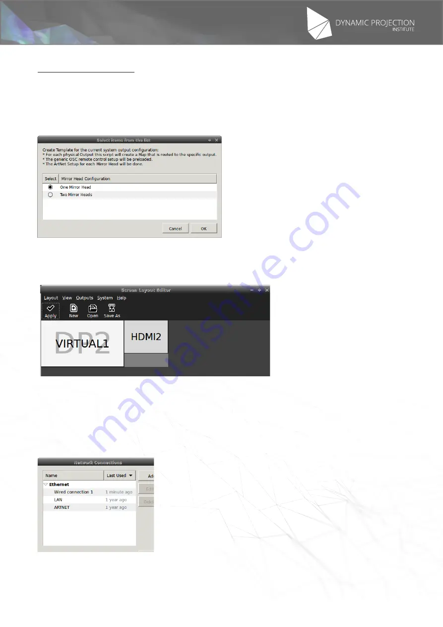
3.6 Physical Outputs:
This is for debugging of outputs only. This tool will show you a representation of the current physical output
configuration. Any modifications wont be safed and executed after a reboot of the system. If at least one physical
output screen is connected to the system the information will show a setup like in the picture below.
Example of the Phyiscal Output debugger. “VIRTUAL1” is the main desktop which is physically connected to
a screen using port “DP2”. The first output screen, which is a Mirror Head unit, is connected to “HDMI2”. The
absence of a screen right of VIRTUAL1 would indicate that there is no physical connection to an output device. In
the case of a MDC-X2 system with two outputs connected there must be two screens right of the VIRTUAL1.
WARNING: THIS SCREEN DOES NOT AUTOUPDATE WHEN A DEVICE IS CONNECTED!
•
3.7 Network Connections:
Starts the basic part of the network manager. Here you can change the LAN IP or add APs for your WiFi
connection. The default IP on the LAN device is 192.168.0.200/255.255.255.0
2.2 MDC-Touch (local access)
Here you can access the MDC-Touch interface in local mode (always available). Usually MDC-Touch is accessed
remotely (if the network licence was purchased) from a tablets, smartphone or any other device in the same network


