background image

Settings via software

Service Instructions 512-211-01/532-211-01 - 00.0 - 06/2016

43

11.14Storing sewing patterns

Standard sewing patterns can be stored on the sewing pattern memory 
buttons 

P1

to

P5

; 50 memory slots are available for this.

The memory slots are accessed using the 

+/- Function

 buttons; memory 

slots up to 25 can also be accessed using the sewing pattern memory but-
tons and combinations thereof.

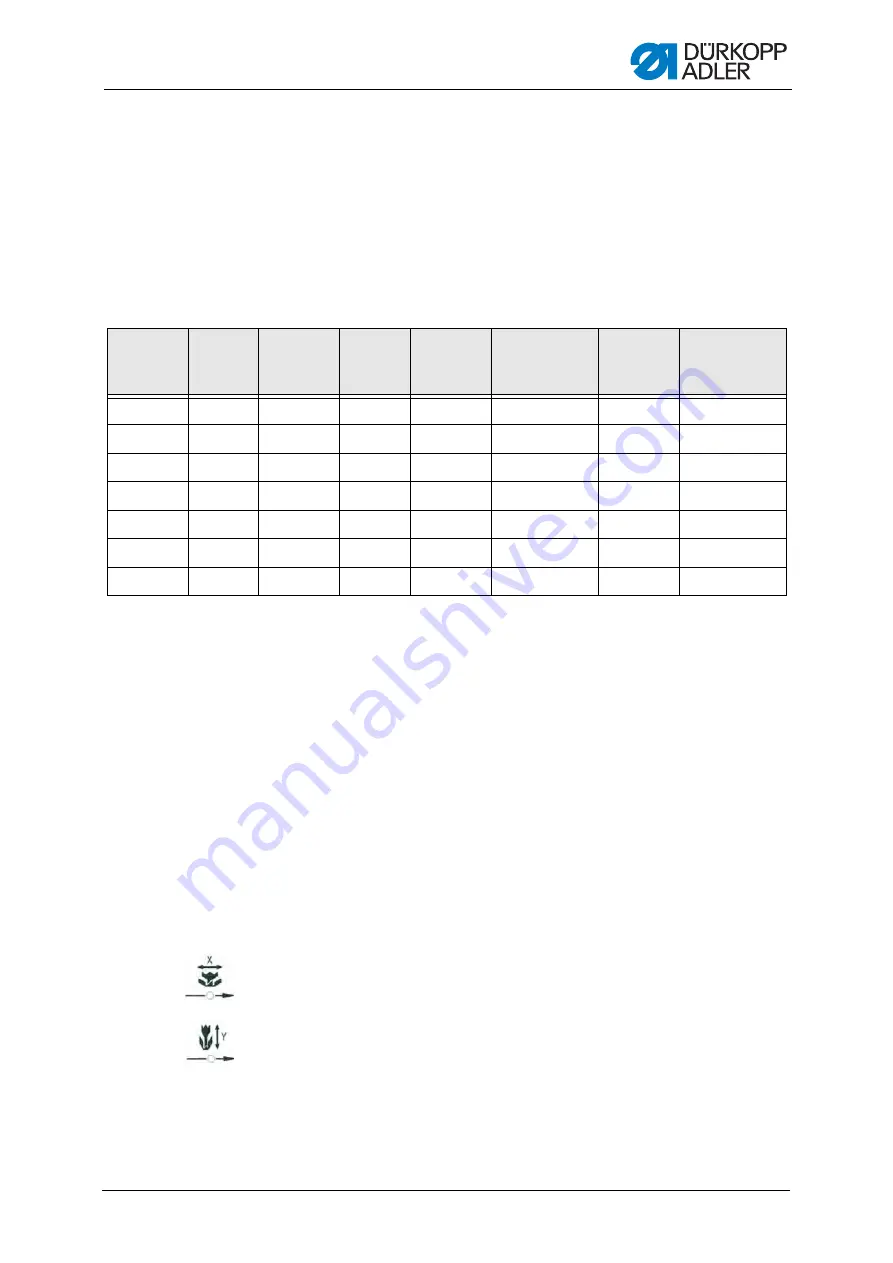
Shortcuts for sewing pattern memory buttons

11.14.1Mapping memory buttons

Prerequisite:

• The machine is in the programming mode, the LED in the 

Ready

 button 

is off.

1.

Press the 

Memory

 and  

P2

 buttons simultaneously.

2.

Press the 

+/- Program

 buttons to select a memory slot.

3.

Press the 

Ready

 button to confirm the memory slot.

4.

Select the sewing pattern (

S. 38

).

5.

Scale the axes (

S. 38

).

6.

Set the speed (

S. 40

).

7.

Moving the position of the sewing pattern:

• Press the 

Selection

 button until the 

X-axis

 LED flashes.

• Press the 

+/- Function

 button and set the values: -5/+5.

• Press the 

Selection

 button until the 

Y-axis

 LED flashes.

• Press the 

+/- Function

 button and set the values: -4 /+4.

8.

Press the 

Ready

 button to confirm the settings.

9.

Press the 

Memory

 button to quit the memory mode.

10. Check the sewing pattern (

S. 40

).

Memory 
slot no.

Shortcut

Memory 
slot no.

Shortcut

Memory 
slot no.

Shortcut

Memory 
slot no.

Shortcut

P1

P1

P8

P1 + P4

P15

P4 + P5

P22

P2 + P3 + P4

P2

P2

P9

P1 + P5

P16

P1 + P2 + P3

P23

P2 + P3 + P5

P3

P3

P10

P2 + P3

P17

P1 + P2 + P4

P24

P2 + P4 + P5

P4

P4

P11

P2 + P4

P18

P1 + P2 + P5

P25

P3 + P4 + P5

P5

P5

P12

P2 + P5

P19

P1 + P3 + P4

P6

P1 + P2

P13

P3 + P4

P20

P1 + P3 + P5

P7

P1 + P3

P14

P3 + P5

P21

P1 + P4 + P5

Summary of Contents for 512-211-01

Page 1: ...Service Instructions 512 211 01 532 211 01 DA_512 211_deen_12 2013 qxd DA 6 pages qxd 04 12 2013 12 38 Uhr Seite 3...

Page 2: ...er AG and protected by copyright Any reuse of these contents inclu ding extracts is prohibited without the prior written approval of D rkopp Adler AG Copyright D rkopp Adler AG 2016 IMPORTANT READ CAR...

Page 3: ...g and closing the hook flap 17 3 3 8 Removing and inserting the throat plate 17 3 4 Surfaces on shafts 19 4 Adjusting the light barriers 21 4 1 Light barrier sensor disks 21 4 2 Adjusting the left and...

Page 4: ...g parameters in level M2 47 11 20 Resetting parameters to factory settings 47 11 21 Editing sewing patterns externally 48 11 22 Working with a USB stick 49 11 23 Error messages 51 11 24 Loading softwa...

Page 5: ...Table of Contents Service Instructions 512 211 01 532 211 01 00 0 06 2016 3 14 2 Circuit diagram 73...

Page 6: ...Table of Contents 4 Service Instructions 512 211 01 532 211 01 00 0 06 2016...

Page 7: ...conventions symbols and characters Various information in this manual is represented or highlighted by the fol lowing characters in order to facilitate easy and quick understanding Correct setting In...

Page 8: ...is unclear indications of right and left are always from the operator s point of view 1 3 Other documents This equipment includes components from other manufacturers Each manufacturer has performed a...

Page 9: ...her suppliers please also observe the safety instructions and the operating manual provided by the respective manu facturer All warnings on the machine must always be in legible condition and may not...

Page 10: ...being used The power plug may only be connected to the power cable by a qualified specialist Work on live components and equipment is prohibited Exceptions are defined in the specifications in DIN VDE...

Page 11: ...ck Risk of puncturing Risk of crushing DANGER Type and source of risk Consequences of non observance Measures for avoiding the risk This is what a warning looks like for a hazard that will result in s...

Page 12: ...warning looks like for a hazard that could result in moderate or minor injury if the warn ing is not complied with CAUTION Type and source of risk Measures for avoiding the risk This is what a warnin...

Page 13: ...y 1 Lay excessively long cables neatly in proper cable snakes 2 Tie the snakes together using a cable tie If possible bind the snakes to fixed parts The cables must be fixed firmly in place 3 Cut off...

Page 14: ...order to access the components at the machine bottom section you must first tilt the machine upper section to the left Fig 1 Tilting the machine upper section to the left and setting it upright NOTIC...

Page 15: ...ing the machine upper section upright 1 Set the upper machine section 1 upright 3 3 2 Removing and fitting the head cover Fig 2 Removing and fitting the head cover Removing the head cover 1 Unscrew th...

Page 16: ...itting the arm cover Removing the arm cover 1 Loosen all 6 screws 1 2 Remove the arm cover 2 Fitting the arm cover 1 Fit the arm cover 2 2 Tighten all 6 screws 1 firmly in place 3 3 4 Removing and fit...

Page 17: ...over 1 Fit the right hand side cover 2 2 Tighten both screws 1 3 3 5 Removing and fitting the left hand side cover Fig 5 Removing and fitting the left hand side cover Removing the left hand side cover...

Page 18: ...and fitting the rear cover Fig 6 Removing and fitting the rear cover Removing the rear cover 1 Loosen all 4 screws 1 on the rear cover 2 2 Remove the rear cover 2 Fitting the rear cover 1 Fit the rear...

Page 19: ...ok flap Opening the hook flap 1 Fold down the hook flap 1 Closing the hook flap 1 Fold up the hook flap 1 3 3 8 Removing and inserting the throat plate Fig 8 Removing and inserting the throat plate 1...

Page 20: ...emove the work surface 4 Fig 9 Removing and inserting the throat plate 2 5 Open the hook flap S 17 6 Loosen the screw 6 7 Unhinge the thread puller blade connecting rod 5 Fig 10 Removing and inserting...

Page 21: ...ke sure that the connecting rod grips properly 3 Tighten all 4 screws 8 of the throat plate firmly in place 4 Tighten the screw 6 5 Close the hook flap S 17 6 Fit the work surface 4 7 Tighten the scre...

Page 22: ...Work principles 20 Service Instructions 512 211 01 532 211 01 00 0 06 2016...

Page 23: ...rect setting The 180 disk points to the front and its lower edge is precisely lined up with the light barriers slots Faults caused by an incorrect setting Damage to fabric wrinkling Incorrect needle p...

Page 24: ...erence by the control unit for the posi tion of the clamps in an X and Y direction Checking the correct setting The clamps are centered in both an X and Y direction Faults caused by an incorrect setti...

Page 25: ...2 Adjust the switching flag 2 accordingly 3 Set the zero point via the control unit 4 Tighten the screw 1 5 Reference the machine 4 3 Thread clamp switching flag The thread clamp switching flag is us...

Page 26: ...Cover Remove the head cover S 13 Fig 16 Adjusting the needle bar height Adjusting steps 1 Use the handwheel to set the needle bar at its lowest position 2 Loosen the screw 1 3 Adjust the height of the...

Page 27: ...eedle The needle must be aligned so that the surface of the groove is parallel to the running direction of the hook tip The hook tip should be located in the lower third of the groove Faults caused by...

Page 28: ...marker line 6 7 is aligned with the needle bar bush 2 Loosen the screw 4 3 Remove the cover ring When doing this make sure that the hook 2 does not work loose and fall 4 Twist the driver 3 accordingly...

Page 29: ...rew 1 2 Loosen the safety screw 3 of the eccentric 3 Adjust the hook path bearing 7 axially with the eccentric 2 Eccentric to the left reduce distance Eccentric to the right increase distance 4 Twist...

Page 30: ...oat plate S 17 Fig 20 Adjusting the blades Adjusting steps 1 Loosen the screw 3 2 Set a distance of 18 5 mm between the front of the throat plate and the thread trimmer lever 5 3 Tighten the screw 3 4...

Page 31: ...hread trimmer Service Instructions 512 211 01 532 211 01 00 0 06 2016 29 5 Move the counter blade and set a distance of 0 5 mm between the needle guide 1 and the counter blade 5 6 Tighten the counter...

Page 32: ...shank shaper Cover 1 Remove the arm cover S 14 Fig 21 Adjusting the height of the fabric clamp lift Adjusting steps 1 Loosen the screw 1 2 Adjust the height by turning the fabric clamp lift on the sh...

Page 33: ...djusting the fabric clamping feet class 512 Faults caused by an incorrect setting The two fabric clamping feet do not raise and lower synchronously Fig 22 Adjusting the fabric clamping feet Adjusting...

Page 34: ...wiper Whendoingthisobservetheminimumdistance of 1 5 mm to the needle and the distance range of 23 to 25 mm when pivoting When using a thin needle set the distance at 23 mm 3 Tighten the screw 1 WARNIN...

Page 35: ...ad strengths small stitch lengths Checking the correct setting 1 Open the hook flap S 17 and observe the thread running around the hook The needle thread loop runs without surplus and without jumping...

Page 36: ...1 Loosen the clamping screw 2 2 Align the actuating lever 4 Smaller fill quantity Push towards bobbin Larger fill quantity Push away from bobbin 3 Tighten the clamping screw 2 Fine adjustment 4 Loosen...

Page 37: ...the adjusting screw 1 10 2 Adjusting the winding tension Correct setting The correct winding tension depends on the anti friction properties and thickness of the thread Faults caused by an incorrect...

Page 38: ...ads a sewing pattern to from a USB stick 2 Needle thread clamp button with LED Fixes needle thread during the first stitch LED on needle thread clamp on LED off needle thread clamp off 3 Memory button...

Page 39: ...The LED in the button illuminates 2 Press the Ready button The LED in the button switches off 7 Program display Displays parameters 8 Program buttons Changes parameters and navigates forwards backward...

Page 40: ...ter storing sewing pat terns S 43 11 5 1 Scaling the X axis 1 Press the Selection button until the X axis LED illuminates 2 Press the Function buttons until the value for the X axis is reached 100 cor...

Page 41: ...ion desired value Example Preset dimension in X direction 16 mm Desired value in X direction 10 mm Value to be set 100 16 mm 10 mm 62 5 Buttonhole gap mm Value Buttonhole gap mm Value Buttonhole gap m...

Page 42: ...The Program display shows the current sewing pattern shape 2 Press the Ready button to confirm the sewing pattern The LED in the Ready button illuminates 3 Press the foot pedal forwards The clamp is...

Page 43: ...the pedal forwards Winding starts 6 To stop winding briefly press the pedal completely forwards 7 Press the Ready button The LED in the button switches off the clamp is raised 11 10Sewing Prerequisit...

Page 44: ...ting sewing 1 Press the Reset button or press the pedal back The sewing process is interrupted the display shows error message E 50 2 To continue sewing press the Reset button or press the pedal for w...

Page 45: ...Press the Ready button to confirm the memory slot 4 Select the sewing pattern S 38 5 Scale the axes S 38 6 Set the speed S 40 7 Moving the position of the sewing pattern Press the Selection button unt...

Page 46: ...1 15Storing sewing pattern sequences Besides the sewing patterns in memory slots P1 P50 the automatic se wing machine also lets you use memory slots C01 C25 Prerequisite The machine is in the programm...

Page 47: ...r completing sewing the Program display shows the further sewing pattern sequence e g 1 2 the Function display shows the next sewing pattern number etc 4 To change between sewing patterns in a sequenc...

Page 48: ...off 1 Press and hold the Memory button for 3 seconds The controller beeps 1x the LED in the button illuminates The Program display shows the parameter numbers the Function display shows the parameter...

Page 49: ...button to save a change The LED in the button switches off 7 Press the Memory button The LED in the button switches off 11 20Resetting parameters to factory settings Prerequisite The machine is in the...

Page 50: ...stitch coordinate in an X and Y direction The ma ximum size of a sewing pattern is 400 x 300 x 1 10 mm Negative values or comma separated values should not be entered The operator does not have to per...

Page 51: ...mat CSV 3 Save the file to a USB stick Information It is also possible to create sewing patterns with DA CAD 5000 and save them as a CSV file 11 22Working with a USB stick Up to 10 of your own sewing...

Page 52: ...g pattern from the USB stick The Function display shows the value ok the controller beeps the sewing pattern is saved 4 Press the Reset button 2x Saving a sewing pattern from the controller to the USB...

Page 53: ...for the Y axis 6 Press the Program buttons to select the next stitch 7 Repeat steps 3 to 5 for all additional stitches 8 Press the Ready button to save the edited sewing pattern 9 Press the Reset butt...

Page 54: ...sition Set main switch to OFF Check sensor E 5 0 1 Data read error Data not available or saved in the wrong format Save the data to a USB stick again E 5 0 2 USB read error MOT file error Save the dat...

Page 55: ...7 Error Z phase Z signal no longer changes Check motor encoder E 7 3 8 Error Z phase Z signal inaccurate encoder has no signal Check motor encoder E 9 0 7 Error search X axis X axis sensor does not re...

Page 56: ...Function display 6 Press the Selection button The process for downloading to the controller starts Important If a value is no longer shown in the Function display the download pro cess is complete No...

Page 57: ...seconds The LED in the button illuminates 2 Select parameter number U085 by using the Program buttons 3 Press the Ready button 4 Enter the function value 1 by using the Function buttons 5 Press the S...

Page 58: ...itch length thread tension curve support etc as well as instructions for accessing and creating sewing programs can be found in the operating manual Operating manual Section 5 Settings via software 12...

Page 59: ...parameter values 2 Press the Program buttons to select other parameters 3 Memory button Processes the memory functions 4 Reset button Deletes an error and restores settings 5 Ready button with LED Ch...

Page 60: ...inates The Program display shows the parameter numbers the Function display shows the values 2 Press the Program buttons to select other parameters 3 Press the Ready button to confirm the parameter Th...

Page 61: ...position 5 Check to see if the hole of the thread puller blade and the needle guide of the throat plate are aligned Fig 33 Checking the hole of the thread puller blade Case A The setting is wrong the...

Page 62: ...0 06 2016 7 Check once again to see if the hole of the thread puller blade and the needle guide of the throat plate are accurately aligned 8 Press the Ready button to save the change The LED in the bu...

Page 63: ...et value 5 in the Function display 6 Press the Selection button The process for downloading to the controller starts Important If a value is no longer shown in the Function display the download pro ce...

Page 64: ...mory button for 6 seconds The LED in the button illuminates 2 Select parameter number U085 by using the Program buttons 3 Press the Ready button 4 Enter the function value 1 by using the Function butt...

Page 65: ...e frequently A clean sewing machine provides protection from faults Points that need to be cleaned particularly thoroughly Area under the throat plate 1 Area around the hook 2 Bobbin housing and inter...

Page 66: ...offices using 1 Underside of throat plate 2 Hook WARNING Risk of injuries due to contact with oil Contact with oil can cause irritation rashes allergies or skin injuries ALWAYS avoid long term contac...

Page 67: ...lso be obtained from D RKOPP ADLER AG sales offices using the following part number 9047 098004 13 2 1 Checking the oil level Checking the oil leven of the hook The sewing automat is equipped with a o...

Page 68: ...1 Unscrew the screw 4 from the oil filler opening at the back of the machine 2 Fill oil through the oil filler opening 3 For lubricating the gear maximum 110 ml are necessary Fig 37 Refilling oil Whe...

Page 69: ...of the machine Abb 38 Lubrication 1 1 Apply an adequate amount of grease to the fleece 2 to lubricate the outer side of the cam disk 1 2 Apply a small amount of grease to the joints 3 to ensure they r...

Page 70: ...0 06 2016 Lubrication points on the machine head Abb 40 Lubrication 3 1 Apply grease to cross head backside 9 and the connectors 10 2 Lubricate the groove 8 3 Lubricate the thread lever guide 7 7 Thr...

Page 71: ...Adjusting steps 1 Loosen and remove the screw 1 The lubricating screw is located underneath the screw The lubrica ting screw presses against the oil wick of the hook lubricator 2 Adjusting the lubrica...

Page 72: ...Maintenance 70 Service Instructions 512 211 01 532 211 01 00 0 06 2016...

Page 73: ...et button Check ROM E 5 0 Pause Reset button pressed while sewing Sewing machine stopped Press the Reset button Actuate the thread trimmer Restart the sewing process E 3 0 2 Error machine head Machine...

Page 74: ...E 7 7 0 3 7 5 Motor signal error Encoder motor has no sig nal Check motor encoder E 7 3 6 Motor rotation error Motor stops encoder has no signal Check motor encoder E 7 3 7 Error Z phase Z signal no l...

Page 75: ...Appendix Service Instructions 512 211 01 532 211 01 00 0 06 2016 73 14 2 Circuit diagram Circuit diagram Sheet 1...

Page 76: ...Appendix 74 Service Instructions 512 211 01 532 211 01 00 0 06 2016 Circuit diagram Sheet 2...

Page 77: ...Appendix Service Instructions 512 211 01 532 211 01 00 0 06 2016 75 Circuit diagram Sheet 3...

Page 78: ...Appendix 76 Service Instructions 512 211 01 532 211 01 00 0 06 2016 Circuit diagram Sheet 4...

Page 79: ...Appendix Service Instructions 512 211 01 532 211 01 00 0 06 2016 77 Circuit diagram Sheet 5...

Page 80: ...Appendix 78 Service Instructions 512 211 01 532 211 01 00 0 06 2016...

Page 81: ......

Page 82: ...Phone 49 0 521 925 00 E mail service duerkopp adler com www duerkopp adler com DA_512 211_deen_12 2013 qxd DA 6 pages qxd 04 12 2013 12 38 Uhr Seite 2 Subject to design changes Printed in Germany D rk...

Reviews: