D-LX 100
Page
15
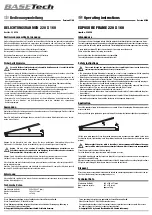
10.4. D-LX 100 Wiring Diagram
7
8
3
1
2
5
4
6
!
lx10
0-
04
-00
4
F2
F1
0 Volt
0 / 4…20mA
D-NG 24/05
PE
L+
L-
L
N
L+
L-
AC-Power Supply
AC Mains
DC Mains
Protective Earth
Protective Earth
Contact Circuit Supply
Not Connected
Plug M2
Flame Message ON
Ready for Operation
Flame Relay K2.2
Fault Relay K1.2
Flame Intensity
sw / BK
gn/ge
GN/YE
ge / YE
ws / WH
gn / GN
gr / GR
L1
N
(Fig. 7)
Wiring diagram: D-LX 100…-P, D-LX 100…/96Ex and D-LX 100…/97Ex
!
The Flame-On-Message has to be supplied via fuse F2 on the “Contact Circuit
Supply” input. Only such components are allowed to be connected to the
output “Read for Operation” which are non-interacting. These components can
be for example the coil of a relay or a magnetic switch.
Then the flame relays contact is protected against contact welding in
accordance with EN 298.
Contacts K1.2 and K2.2 must be switched in series if the additional safety requirements for direct
shut-off of the entire fuel supply are to be fulfilled. These are specified in VDE0116, paragraph 8.7.2
/10.98 or TRD 604, pages 1 and 2 for 72-hour operation (steam boiler without constant supervision).