


D-LX 100
Page
5
If the cause of the error is a defect in the integrated flame scanner,
the red and green LED’s will blink alternately.
Pressing the reset button on the front panel of the D-LX 100 acknowledges a fault in the unit and
allows flame scanning functions to continue after restart. When the reset button is pressed, all LEDs
will go off. It is also possible to reset the unit by open the plug connection or by interrupting the yellow
24 V supply wire for a short moment. In this case the cover of the flame scanner don’t has to be
opened in order to get access to the reset button.
If the power supply is interrupted or the reset button is pressed, the relays are released, regardless of
the status of the unit (flame signal ON / OFF or fault). The flame scanning program is then restarted.
Note:
The D-LX 100 is an officially approved flame scanner. Any tampering or modifications will lead to a
loss of its approved status. Repairs may only be performed by the manufacturer or its authorized
service outlets.
6. Installation
Installation occurs according to the D-LX 100 dimensional drawings. The electrical installation must
be performed in accordance with the wiring diagram in this manual, as well as any local guidelines.
The location of fuses F1 and F2 can be found in the dimensional drawing.
The enclosure rating of the flame scanner is IP67 if it is a model with the plug connection, and IP65 if
the scanner has a permanently threaded cable connection.
D-LX 100
9
0
9
0
D-ZS 087
D-ZS 087
V2
V1
No6
No4
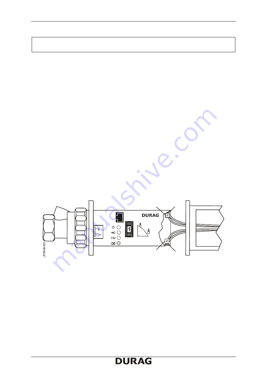
F2 = Flame contact fuse
F1 = Mains fuse
(Fig. 3)
Location of fuses
Note:
To change the amplification or to replace the fuses, the electronics must be pulled from the
housing. Due to the D-LX 100‘s compact design, one must observe that no wires get pinched when
putting the scanner back together. The housing should be closed without using excessive force.


