- 89 -
5.0 MAINTENANCE
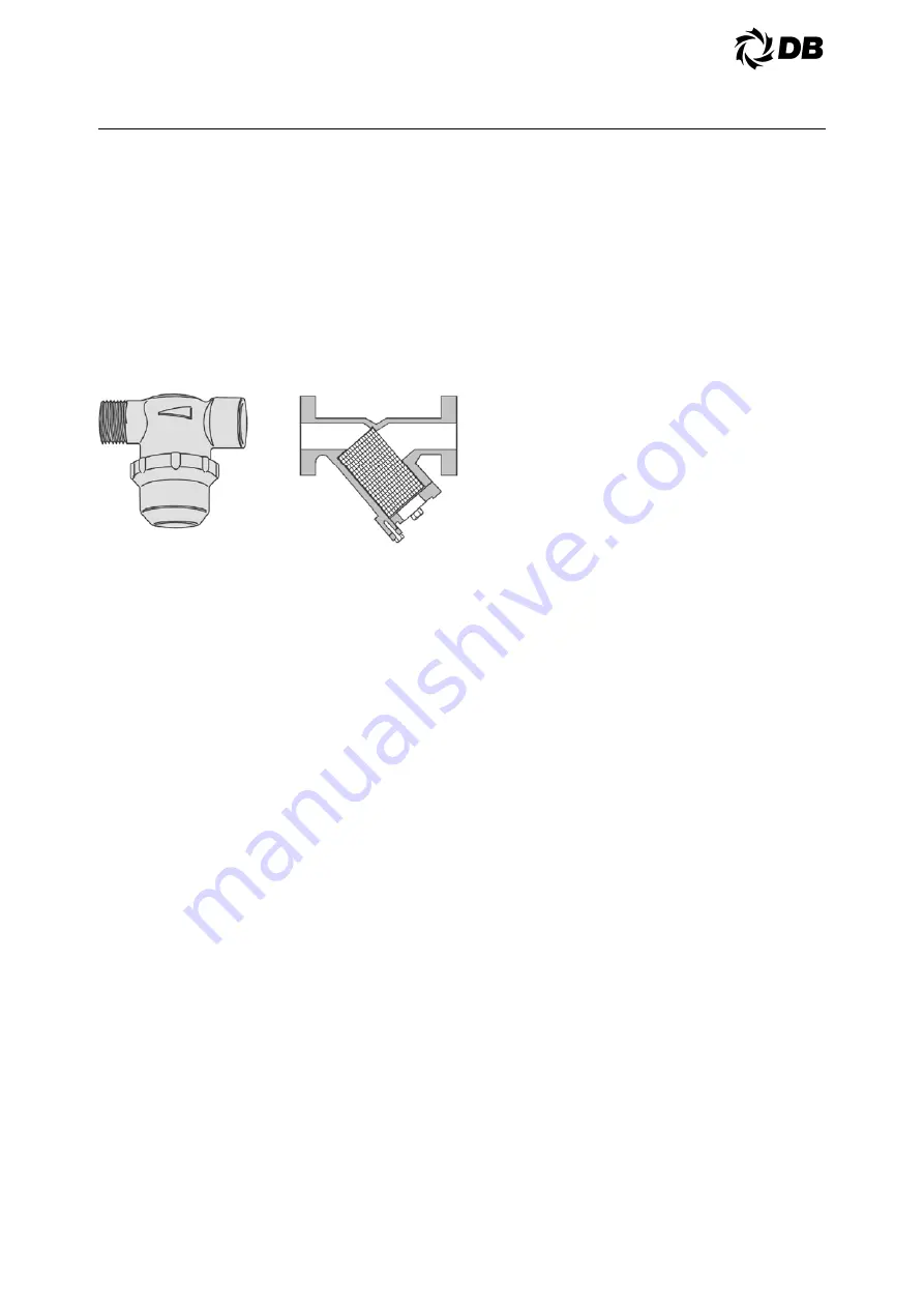
5.4.2.2. Strainers
If any of the media contains particle
larger 1mm (0.04 inch), we recommend
that a strainer with a size of 16-20
mesh (number of openings pe inch) is
installed before the exchanger.
The particles could otherwise block the
channels, causing bad performance,
increased pressure drop and risk of
freezing.
5.5 AIR COOLED CONDENSER
CLEANING
The face of the condenser should be cleaned at
least once month during operation. If conditions
are bad and condensers pick up dirt very quickly,
it is suggested that they can be cleaned more
frequently.
If the condenser is allowed to get too dirty, the
unit will run at high head pressure and will not
give satisfactory performance.
Dirty coils can be cleaned using a soft brush or by
flushing with cool water or commercially available
coil cleaners.
DO NOT USE HOT WATER OR STEAM. To do
so will cause excessive pressure in the system.
The face of the condenser should be cleaned at
the beginning of the season and periodically
thereafter if conditions require.
5.6 ELECTRICAL
MALFUNCTION
The unit has four devices designed to protect
compressor motors and manual motor controllers
from electrical malfunctions: Circuit breakers.
starter overload relays, under voltage relay
(optional), and motor over temperature protectors.
If the under voltage relay trips, it is a sign of
trouble in incoming power. If it trips again after
resetting, call your electric utility to investigate the
problem. If circuit breaker or motor overload relay
or motor over temperature protectors trip, this is a
sign of possible motor trouble. DO NOT reset and
try to run compressor again. Call authorized
service representative to check for motor trouble.
Resetting these safety devices and repeated
starting could turn a minor motor problem into a
costly major motor burnout.
5.7 REFRIGERANT
CHARGE
5.7.1 GENERAL
All packaged chiller units are given a
complete charge of refrigerant at the
factory. The type and amount of
refrigerant required is in Physical
Specifications. The total refrigerant
shown is for the entire system. Since
these units have separate circuits, each
circuit should be considered separately
for charging.
In order to check proper refrigerant
charge, look in each liquid line sight glass
with the aid of a flashlight during system
operation. At all operating conditions, the
sight glass should be clear. If bubbles are
visible at any operating condition, the
circuit is short of charge.
Be careful not to overcharge the machine.
overcharging will result in considerable
liquid logging in the condenser, and
excessive condensing pressure.
To add refrigerant, connect a refrigerant
vessel to the 1/4" [6.4mm] back seating
port of the suction valve. Purge the air
from the tube with refrigerant gas before
connecting. With the unit running, open
the refrigerant vessel vapor connection
slightly. If the refrigerant vessel is warmer
than the evaporator, refrigerant will more
readily flow from the vessel into the unit.
5.7.2 AIR COOLED PACKAGES
To determine the proper refrigerant
charge, check the amount of subcooling if
possible. The amount of subcooling at the
liquid line (liquid line saturation
temperature corresponding to liquid line
pressure minus liquid line temperature)
should be between 15°F [8.3°C] and 20°F
[11.1°C]. Subcooling at the condenser
out-subcooler inlet trap should not exceed
5°F [2.8°C]. This sight glass should be
clear with no bubbles.
Summary of Contents for ACDS
Page 7: ...7 2 0 INSTALLATION FIGURE 2 3 2 ACDS RIGGING ACDS 010 ACDS 020...
Page 8: ...8 2 0 INSTALLATION ACDS 030 040 050 060 070 ACDS 080 090 100 120 ACDS 135 150 165 180...
Page 9: ...9 2 0 INSTALLATION FIGURE 2 4 2B DIMENSIONAL DATA ACDS 010...
Page 10: ...10 2 0 INSTALLATION ACDS 020...
Page 11: ...11 2 0 INSTALLATION ACDS 030...
Page 12: ...12 2 0 INSTALLATION ACDS 040...
Page 13: ...13 2 0 INSTALLATION ACDS 050 060 070...
Page 15: ...15 2 0 INSTALLATION ACDS 100 120...
Page 19: ...19 2 0 INSTALLATION ACDS 030 040 050 060 070 ACDS 080 090 100 120 135 150 ACDS 165 180...
Page 22: ...22 2 0 INSTALLATION FIGURE 2 7A FIGURE 2 7B FIGURE 2 7C FIGURE 2 7D FIGURE 2 7E...
Page 25: ...25 3 0 OPERATION FIGURE 3 2 1 TYPICAL PIPING SCHEMATIC ACDS 010 020 030...
Page 26: ...26 3 0 OPERATION ACDS 040 050 060 070...
Page 27: ...27 3 0 OPERATION ACDS 080 090 100 120...
Page 28: ...28 3 0 OPERATION ACDS 135 150...
Page 29: ...29 3 0 OPERATION ACDS 165 180...
Page 54: ...54 4 0 ELECTRICAL 4 9 TYPICAL WIRING SCHEMATIC ACDS 010...
Page 55: ...55 4 0 ELECTRICAL...
Page 56: ...56 4 0 ELECTRICAL ACDS 020...
Page 57: ...57 4 0 ELECTRICAL...
Page 58: ...58 4 0 ELECTRICAL ACDS 030...
Page 59: ...59 4 0 ELECTRICAL...
Page 60: ...60 4 0 ELECTRICAL ACDS 040...
Page 61: ...61 4 0 ELECTRICAL...
Page 62: ...62 4 0 ELECTRICAL ACDS 050 060 070...
Page 63: ...63 4 0 ELECTRICAL...
Page 64: ...64 4 0 ELECTRICAL ACDS 080 90...
Page 65: ...65 4 0 ELECTRICAL...
Page 66: ...66 4 0 ELECTRICAL...
Page 67: ...67 4 0 ELECTRICAL...
Page 68: ...68 4 0 ELECTRICAL ACDS 100...
Page 69: ...69 4 0 ELECTRICAL...
Page 70: ...70 4 0 ELECTRICAL...
Page 71: ...71 4 0 ELECTRICAL...
Page 72: ...72 4 0 ELECTRICAL ACDS 120...
Page 73: ...73 4 0 ELECTRICAL...
Page 74: ...74 4 0 ELECTRICAL...
Page 75: ...75 4 0 ELECTRICAL...
Page 76: ...76 4 0 ELECTRICAL ACDS 135...
Page 77: ...77 4 0 ELECTRICAL...
Page 78: ...78 4 0 ELECTRICAL...
Page 79: ...79 4 0 ELECTRICAL...
Page 80: ...80 4 0 ELECTRICAL ACDS 150...
Page 81: ...81 4 0 ELECTRICAL...
Page 82: ...82 4 0 ELECTRICAL...
Page 83: ...83 4 0 ELECTRICAL...
Page 84: ...84 4 0 ELECTRICAL ACDS 165 180...
Page 85: ...85 4 0 ELECTRICAL...
Page 86: ...86 4 0 ELECTRICAL...
Page 87: ...87 4 0 ELECTRICAL...


