


Soft Serve Freezer Model GES-102
184559
33
9
Assembly
(continued)
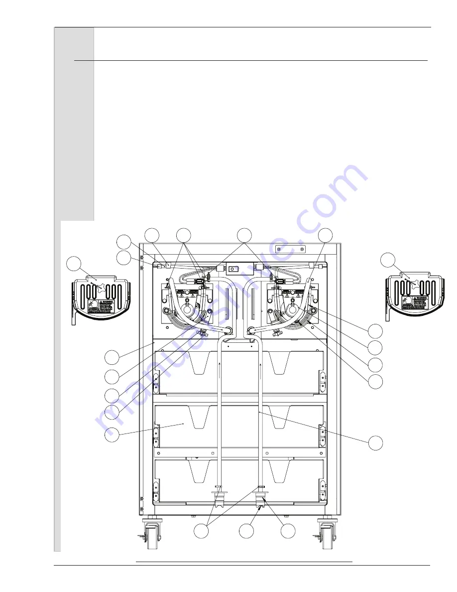
Important:
Do not twist the hose assembly while
installing.
16. Check to ensure the transfer hose
is straight and centered on the roller
assembly by observing the locating
line. The line should be in the same
position at the inlet and outlet guides
of the roller bearing support, as shown
in figure 9-6.
17. Swing the shoe over hose and tighten
the swing clamp hand knob in place.
18. Insert the air tube into the retainer in
the top of the cabinet.
19. Insert sensor probe in to top cab wall
and mix inlet housing.
20. Insert the MTS cover over stud. Hose
clamps should be exposed. Tighten
cover knob. Hand tighten only.
21. Loop the braided hose towards you
and slide the hose over the cylinder
inlet tube. Tighten the clamp. Make
sure the braided hose is not twisting
transfer hose.
Important:
The MTS will not operate unless the
cover is installed and secured by the
hand knob.
MIX FLOW
MIX FLO
W
MIX FLOW
MIX FLOW
AIR METER
AIR TUBE
RETAINER-AIR LINE
TUBE-MIX INLET
ADAPTER-MIX BAG
1
SUPPORT-ROLLER BEARING
2
3
ROLLER-ASSY COMPLETE
4
KNOB-HAND
5
ARM-SWING CLAMP
M02079rev4
6
7
8
9
CLAMP-SOFT HOSE
10
COVER-MTS
12
HOSE-TRANSFER RED LINE
13
14
DUCKBILL-INLET
15
PORT-AIR/MIX INLET
18
SHOE-SPRING
16
19
MIX FLOW
17
CLAMP-RATCHET
20
AIR CURTAIN
SWITCH
ROLLER SHOE
HOSE-ASSY MIX BRAIDED
11
11
MIX DRAWER
COVER-MTS
Figure 9-6 MTS
Summary of Contents for GES-102
Page 2: ......
Page 10: ......
Page 20: ...Soft Serve Freezer Model GES 102 10 184559 5 Part Names and Functions Figure 5 1 Head Assembly...
Page 82: ......
Page 84: ......
Page 105: ......
Page 106: ...Soft Serve Freezer Model GES 102 22 184559 O Ring Chart...
Page 107: ......