


Soft Serve Freezer Model GES-102
184559
31
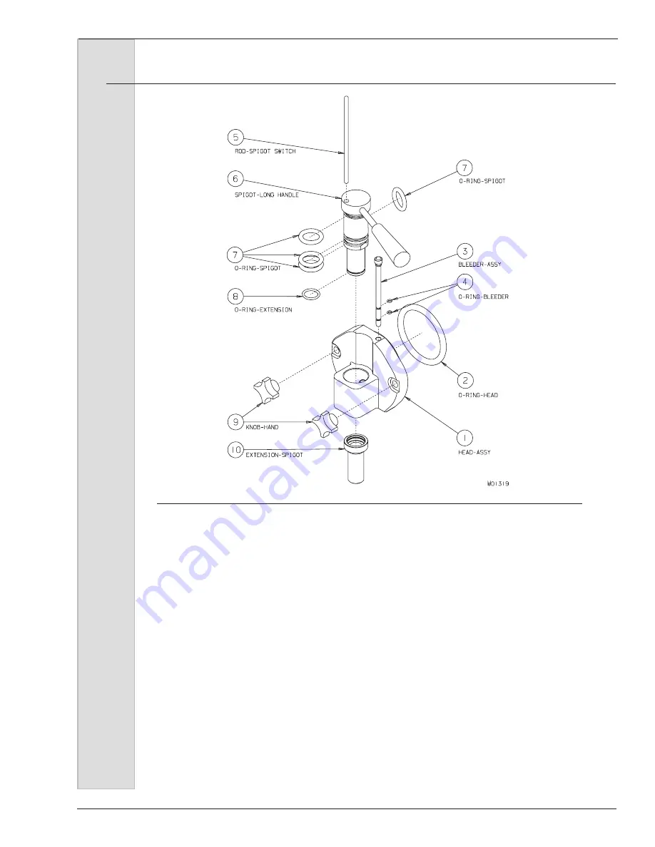
Figure 9-4 Head Assembly
4. Insert the assembled beater shaft into
the cylinder by placing the rear blade
on the bottom of the cylinder. This will
center the beater and allow alignment
with the drive coupling. Slide beater
shaft into cylinder until shaft engages
drive coupling. Repeat for second
cylinder assembly.
5. Lubricate the inside surface of the
cylinder bushings and place on the
end of the beater shaft assemblies.
The bushings will slide on only one
way.
6. See figure 9-4. Install and lubricate
the o-rings (see o-ring chart, last
page) on the dispensing spigots (7)
and insert the spigots into the head
(1). Check by turning the spigots side
to side, making sure they move freely.
7. Place the extension or holding o-ring
(8) onto the spigots. Do not lubricate
this o-ring.
8. Install and lubricate the 4” head
o-rings(2).
9. Install and lubricate the o-rings (4)
on the air bleed plugs (3). Insert the
plugs in the head assemblies (1).
10. Install the dispensing head onto the
freezer by aligning the studs with the
holes in the head and sliding toward
the freezer. Finger-tighten the hand
knobs evenly.
Important
:
Excessive force will damage the head.
Do not use tools to tighten.
—continued
9
Assembly
(continued)
Summary of Contents for GES-102
Page 2: ......
Page 10: ......
Page 20: ...Soft Serve Freezer Model GES 102 10 184559 5 Part Names and Functions Figure 5 1 Head Assembly...
Page 82: ......
Page 84: ......
Page 105: ......
Page 106: ...Soft Serve Freezer Model GES 102 22 184559 O Ring Chart...
Page 107: ......