Installation
057-230 ISSUE: 1
Page 32 of 100
3.1.4.1
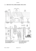
CT CONNECTIONS
p1,
k
or K is the primary of the CT that ‘points’ towards the GENERATOR
p2,
l
or L is the primary of the CT that ‘points’ towards the Load
s1 is the secondary of the CT that connects to the DSE Module’s input for the CT measuring
s2 is the secondary of the CT that should be commoned with the s2 connections of all the other CTs
and connected to the CT common terminal of the module.
TO GENERATOR
TO LOAD
POLARITY OF CT PRIMARY
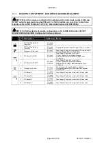
3.1.5
CONFIGURABLE DIGITAL INPUTS
NOTE: For further details of module configuration, refer to DSE Publication:
057-223
DSE6010 MKII & 6020 MKII Configuration Software Manual.
Pin
No
Description
Cable
Size
Notes
38
Configurable Digital Input A
0.5 mm²
AWG 20
Switch To Negative
39
Configurable Digital Input B
0.5 mm²
AWG 20
Switch To Negative
40
Configurable Digital Input C
0.5 mm²
AWG 20
Switch To Negative
41
Configurable Digital Input D
0.5 mm²
AWG 20
Switch To Negative
42
Configurable Digital Input E
0.5 mm²
AWG 20
Switch To Negative
43
Configurable Digital Input F
0.5 mm²
AWG 20
Switch To Negative
Labelled as
p1,
k
or K
Labelled as
p2,
l
or L

