Maintenance
8-3
Heat Transfer Fluid “HTF”
•
A clean, properly maintained hot water system should not be drained unless there is a
possibility of freezing, the boiler has accumulated a considerable amount of sludge or
dirt on the water side, or draining is necessary to perform repairs. Very little sludge
should accumulate in a water heater where little make-up water is added and where an
appropriate water heater water treatment is maintained at proper strength.
•
The “HTF” should be tested from year to year for freeze protection and should be
strong enough for your area. The “HTF” should be checked with a refractometer.
Check the glycol/water mixture chart (see “Setup, Heat Transfer Fluid) for the mixing
ratios.
•
The “pH level” of the “HTF” requires an annual check to see if the pH level is
neutral. The pH level should be at #7. This should be checked with a pH instrument.
Note: See “Setup, Heat Transfer Fluid HTF, Heat Transfer Fluid specifications” for
complete fluid specifications.
Burner
•
For burner seasonal maintenance, see the “Service Manual”.
“Y” Strainer
“Y” Strainer Flush
•
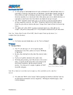
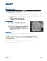
The “Y”-strainer
figure 47
(2-1) requires regular
maintenance every time system is set up or 1000 hours
of operation.
•
Remove the end plug from the end of the strainer outlet
valve.
•
Position a 5-gallon container at the outlet valve.
•
With the pump running, crack the strainer valve several
times. A quick on/off action of the valve will provide
short bursts required to backwash and clean the
strainer. The removal of a couple of gallons of “HTF”
should be adequate.
Note: Be certain not to run the reservoir empty, as this would allow air to enter the
system.
•
The extracted “HTF” can be reused. Before pouring the fluid back into the reservoir,
the fluid must be filtered to remove impurities. Filtering the fluid through a cotton
cloth is adequate.
Figure 47-Back Washing Y-Strainer
Summary of Contents for 600 GTS Series
Page 2: ......
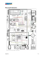
Page 47: ...Appendix 9 3 Electrical Schematics Figure 56 600 GTS sub 40 Electrical Schematic...
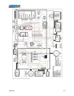
Page 48: ...Appendix 9 4 Figure 57 600 GTS Electrical Schematic...
Page 49: ...Appendix 9 5 Figure 58 HR2250 Electrical Schematic...
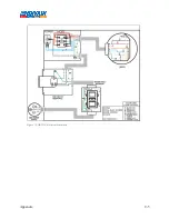
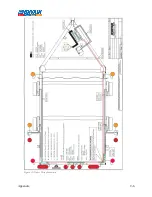
Page 50: ...Appendix 9 6 Figure 59 Trailer Wiring Schematic...

