Troubleshooting (CME)
7-2
Eventually the system may have to be drained and the filter screen removed and
cleaned by hand (see Y-strainer screen in Maintenance section of Operators Manual).
Check that pressure bypass valve is open if fluid receiving units are closed off.
•
When performing “ground thaw” or “concrete cure” application, the use of only one
“heat exchanger loop” may result in inadequate flow. Utilizing at least two “heat
exchanger loops” will provide adequate flow...or a short bypass loop can also be
incorporated to correct this situation.
•
Air present in the circulation system. Air in the system can cause cavitation in the
pump and pressure loss. Refer to “Operation, Purging air from the system” for air
purging instructions.
•
Supply temperature overrun causing vaporization (steam) and pump pressure to be
lost. Cavitation will occur in the “water heater heat exchanger” causing a noticeable
bubbling, popping sound. Check the “overflow outlet” to confirm presence of fluid
vapor. If vaporization is occurring, the “aquastat” setting is set too high. Reset the
“aquastat” to a lower temperature (10°F increments) and allow cool down. When the
“heat transfer fluid” cools down, the system will regain pump pressure. Allow the
burner to cycle back on and observe to ensure that the vaporization situation does not
reoccur. If it does reoccur, reset the “aquastat” to a lower temperature until the
problem is rectified.
Note: This situation will occur more often in a “low flow” situation (refer to Operation,
Temperate Start Procedure, Control Settings).
c)
Defective flow switch. If a) and b) check out good, the flow switch will need to be re-
calibrated, or replaced.
No Power at Aquastat
Check for 120-volt power between letter N and #6 terminal strip. If no power, check the
following:
a)
Check setting on aquastat.
b)
Check sensor and verify that it is intact in its well.
c)
If a) and b) check out good, replace both aquastat and sensor.
No power at Outgoing Side of High Limit Switches
Check for 120-volt power between letter N and #5 terminal strip. If no power, check the
following:
a)
Manual reset high limit button tripped.
b)
Check settings of switches. The automatic high limit should be set 10 F higher than the
set point of the aquastat and the manual reset high limit should be set 10 F higher that the
automatic high limit switch.
c)
Determine which high limit switch is defective and replace.
Summary of Contents for 600 GTS Series
Page 2: ......
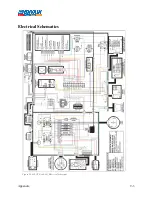
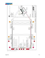
Page 47: ...Appendix 9 3 Electrical Schematics Figure 56 600 GTS sub 40 Electrical Schematic...
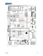
Page 48: ...Appendix 9 4 Figure 57 600 GTS Electrical Schematic...
Page 49: ...Appendix 9 5 Figure 58 HR2250 Electrical Schematic...
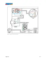
Page 50: ...Appendix 9 6 Figure 59 Trailer Wiring Schematic...

