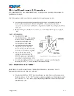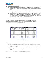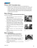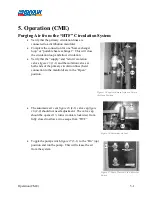
Operation (CME)
5-7
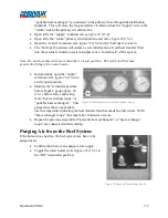
“portable heat exchanger” is connected to the primary lines through the distribution
manifold. This will close the loop and allow circulation from the “supply” side to the
“return” side of the primary circulation line.
•
Open fully the “supply” isolation valves
figure 29
(15-2).
•
Open fully the “return” primary circulation line and valve
figure 29
(15-3).
•
Open the “return” isolation valve
figure 29
(15-4) to the “half open” position.
•
The “half open” position will ensure a slow introduction of cold heat transfer fluid
into the external circulation system and prevent a “cold-shock” of the system.
Note: Do not close this valve more than the ½ closed position. The restricted flow may
prevent the firing of the water heater.
•
Incrementally open the “return”
isolation valve
figure 29
(15-4) to
a fully open position.
•
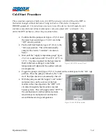
Monitor the “return temperature
before bypass” gauge
figure 30
(16-1) before fully connecting
more “heat exchanger loops” or
“portable heat exchangers”. This
gauge must show a noticeable
rise in temperature indicating the heat transfer fluid has made the full circuit. With
“heat exchanger loops”, this may take 10 minutes or more.
•
Repeat the previous step until all “portable heat exchangers” or “heat exchanger
loops” are connected and circulating.
Purging Air from the Fuel System
If the burner does not fire, the fuel system may have to be
purged of air.
•
Confirm that there is an adequate fuel supply.
•
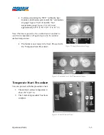
Toggle the water heater switch
figure 31
(17-2) to
the “Off” downward position.
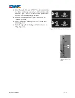
Figure 30-Return Temperature Before Bypass Gauge
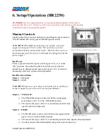
Figure 31-Pump & Water Heater Switch
Summary of Contents for 600 GTS Series
Page 2: ......
Page 47: ...Appendix 9 3 Electrical Schematics Figure 56 600 GTS sub 40 Electrical Schematic...
Page 48: ...Appendix 9 4 Figure 57 600 GTS Electrical Schematic...
Page 49: ...Appendix 9 5 Figure 58 HR2250 Electrical Schematic...
Page 50: ...Appendix 9 6 Figure 59 Trailer Wiring Schematic...

