Operation (CME)
5-5
•
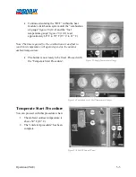
Continue circulating the “HTF” within the heat
module’s distribution system until the “combustion
air gauge”
figure 26
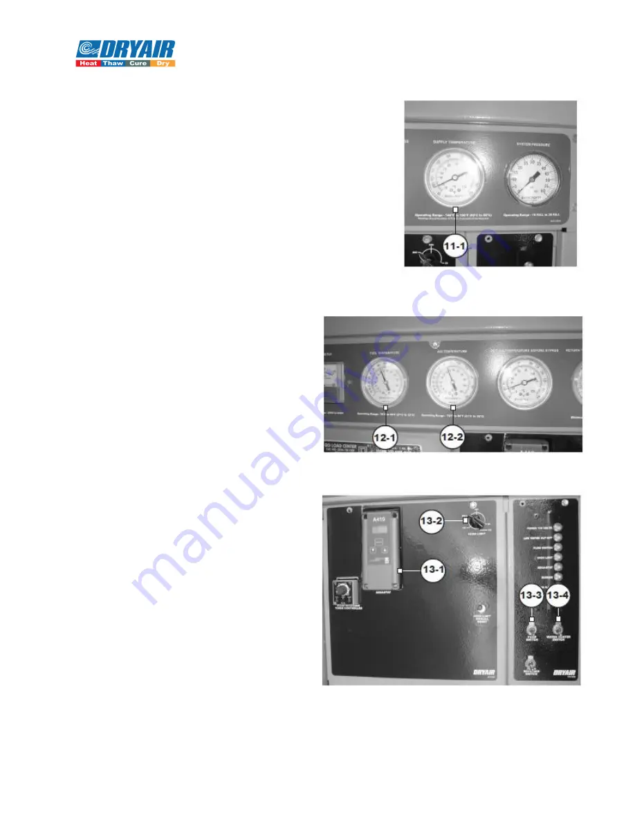
(12-2) and the “fuel
temperature gauge”
figure 26
(12-1) read
approximately 60° F to 70° F (15° C to 21° C).
Note: The time required for the combustion air and fuel to
reach this temperature will again depend on the outdoor
ambient temperature.
•
The burner is now ready to be fired. Proceed with
the “Temperate Start Procedure”.
Temperate Start Procedure
You can proceed with this procedure when:
1.
The ambient outdoor temperature is
above 50° F (10° C).
2.
The “cold start procedure” has been
complete.
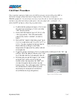
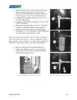
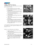
Figure 25-Supply Temperature Gauge
Figure 26-Combution Air & Fuel Temperature Gauges
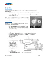
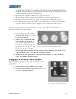
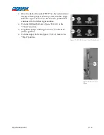
Figure 27-600 GTS Control Panel
Summary of Contents for 600 GTS Series
Page 2: ......
Page 47: ...Appendix 9 3 Electrical Schematics Figure 56 600 GTS sub 40 Electrical Schematic...
Page 48: ...Appendix 9 4 Figure 57 600 GTS Electrical Schematic...
Page 49: ...Appendix 9 5 Figure 58 HR2250 Electrical Schematic...
Page 50: ...Appendix 9 6 Figure 59 Trailer Wiring Schematic...

