background image


Appendix 


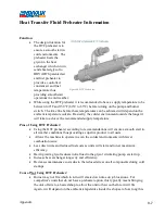
will take but in any event, it will take much longer compared to using the preheater 
on the DRYAIR unit. 


If the unit does start in cold temperatures, there is potential for the heat exchanger to 
accumulate soot due to not having a controlled environment of air and fuel going into 
the burner.  Sooting will stop after the unit warms up if the settings on the burner are 
correct.  Every 1 mm of soot accumulated on the heat exchanger results in a 5% loss 
of efficiency compared to a clean exchanger.  Running the preheater on the DRYAIR 
unit eliminates the need to adjust burner settings in reaction to changing weather 
conditions. 


Decreases heat exchanger service life. 


Increases maintenance costs due to added stress on all components during cold 
startups. 
 

In Conclusion: 

Using the preheater as instructed in the manual will allow you to operate DRYAIR units in 
colder climates without sacrificing efficiency or long term reliability of the unit.  DRYAIR 
recommends planning ahead and starting the preheater to allow it to run while the units is in 
transit to the jobsite (running on generator power) and while operators are reeling out and 
placing hose on the site.  This will still make for productive use of the time while allowing the 
unit to benefit from the patented preheater feature.  If the operator decided they do not want to 
wait for the preheater to work, the DRYAIR unit will perform just like any of our competitor’s 
units that do not have a preheater option. 


9-8

Summary of Contents for 600 GTS Series

Page 1: ...Operator Manual Central Mobile Enclosure 600 GTS Series S N 154801 DRYAIR Manufacturing Corp Box 126 400 Service Road St Brieux SK Canada S0K 3V0 Tel 306 275 4848 1 888 750 1700 Fax 306 275 4664...

Page 2: ......

Page 3: ...assive Heat Transfer Circulation Line Heat Exchangers Hose Reel Accessories Mixing Booster Pump Optional Remote Manifold Insulated Line Jackets Portable Heat Exchanger How the System Works 4 Setup CME...

Page 4: ...Central Heating Module 8 1 Daily Checklist 8 1 Check for Strong Odor of Gas 8 1 Check Heat Transfer Fluid HTF Level Everyday 8 1 Check the Supply Temperature Gauge 8 1 Seasonal Checklist 8 1 HR2250 8...

Page 5: ...he Closed Position 5 2 Figure 21 Fuel Return Valve 5 3 Figure 22 Fuel Supply Valve Filter 5 3 Figure 23 600 GTS Control Panel 5 4 Figure 24 600 GTS Breaker Box 5 4 Figure 25 Supply Temperature Gauge 5...

Page 6: ...iter Adjustment 8 6 Figure 51 Torque Limiter Assembly 8 6 Figure 52 Gear Box 8 7 Figure 53 Non Pressure Vessel Decal 9 1 Figure 54 TUV SUD Certification Label 600 GTS 9 2 Figure 55 TUV SUD Certificati...

Page 7: ...parts will be warrantied for 90 days from the repair date Bill of sale must accompany the warranty claim The terms of this Warranty Policy are subject to provincial and state legislation DRYAIR reser...

Page 8: ...verage through their own manufacturer Please refer generator issues to the OEM Contact information may be found in the Service Operator Manual under Optional Equipment Owner Obligations It is the resp...

Page 9: ...edule numbered unit Warranty parts are to be tagged with a warranty claim number When claiming for warranty labour the allowable warranty labour rate will be 65 00 hour The factory reserves the right...

Page 10: ...iping and fuel accessories The water heater housing panels must be kept closed when the system is operating This prevents drafts from affecting water heater operation Heat Transfer Fluid Follow the fo...

Page 11: ...lation Remove to fresh air if effects occur Consult a physician Note to physician No specific antidote Supportive care Treatment based on judgment of the physician in response to reactions of the pati...

Page 12: ...n system No special boiler certification is required to operate the system Circulation system automatic air vent component for quick setup and go operation A central heat module control center which m...

Page 13: ...old up to 4000 ft of the 5 8 I D circulation line heat exchangers The reel provides convenient storage for the circulation line heat exchange hose required for thawing and or curing concrete The elect...

Page 14: ...ed jackets will prevent exposed circulation line heat loss in extreme subzero conditions Portable Heat Exchanger Portable heat exchangers are the ideal way to heat and or dry enclosed structures Their...

Page 15: ...at transfer fluid flows through the transfer coil where heat is transferred to the air being drawn through the coil by the fan The coil is specially designed for optimum heat transfer without adding a...

Page 16: ...able heat exchangers or circulation line heat exchangers higher than the top level figure 9 2 2 of the heat transfer fluid fill tank If this is not observed the following can occur Insufficient fluid...

Page 17: ...nection to be made is a 115 230VAC service outlet The main feed wiring must be adequately sized to carry the minimum ampacity shown on the water heater cabinet s rating label All electrical connection...

Page 18: ...ee Safety Concerns section MSDS sheets for additional information Soft water with a pH level 7 must be used CAUTION Whenever coupling or uncoupling quick couplers make sure that the isolation valves a...

Page 19: ...bly 3 Disconnect the oil supply hose figure 13 7 1 and oil return hose figure 13 7 2 by unscrewing the fuel line connections on the side of the burner The loose supply and return hose ends should be p...

Page 20: ...ecting the 1 2 and the green yellow wires to the control box on the burner assembly figure 12 6 1 Once the wires have been reconnected slip the water tight connection figure 12 6 2 into the burner cha...

Page 21: ...the isolation valves at both ends of the primary circulation lines hard connection to the manifold are in the Open position The automatic air vent figure 16 2 1 valve cap figure 16 2 2 should not need...

Page 22: ...ure gauge figure 19 5 1 will hold at a steady reading of between 15 to 40 P S I Before Firing the System Verify that the power supply is correct and that the electrical hook up is as specified in Setu...

Page 23: ...line valves figure 21 7 1 and figure 22 8 1 are in the positions as shown to the right Verify that the heat transfer fluid level gauge figure 18 4 1 shows approximately full Figure 21 Fuel Return Val...

Page 24: ...old start circulation heater Wait until the supply temperature gauge figure 25 11 1 reads between 80 F to 90 F 27 C to 32 C The time required for the heat transfer fluid in the heat exchanger to reach...

Page 25: ...ombustion air and fuel to reach this temperature will again depend on the outdoor ambient temperature The burner is now ready to be fired Proceed with the Temperate Start Procedure Temperate Start Pro...

Page 26: ...ing two or more portable heat exchangers or three or more circulating line heat exchanger loops Set the aquastat figure 27 13 1 at 190 F 88 C and the high limit switch figure 27 13 2 between 200 F 210...

Page 27: ...prevent the firing of the water heater Incrementally open the return isolation valve figure 29 15 4 to a fully open position Monitor the return temperature before bypass gauge figure 30 16 1 before f...

Page 28: ...hen the fuel system is primed the fuel pressure gauge figure 33 19 2 will show a steady reading and the water heater should attempt to ignite Note The reset process can be tried up to six times at the...

Page 29: ...the HTF into the system By watching the glycol level gauge figure 38 24 1 continue to fill the system until the glycol level gauge shows full Note Caution must be taken when approaching the full mark...

Page 30: ...5 21 1 to the Closed position and continue with the following procedures Turn the fill drain ball valve figure 36 22 2 to the Closed position Toggle the pump switch figure 37 23 1 to the Off down posi...

Page 31: ...hen the power switch figure 39 1 1 is in the On position By connecting the foot switch you can load or unload hose by depressing the foot switch figure 39 1 2 which is momentary will only operate when...

Page 32: ...or The electric motor used to drive the reel is manufactured by Marathon Electric No regular maintenance is required Low temperature manual reset thermal protector Totally enclosed and full gasket con...

Page 33: ...le servicing the unit See Maintenance Gear Box section of the operator s manual for Hub City Gear Box oil filling procedures service and maintenance Torque Limiter Clutch The Torque limiter protects t...

Page 34: ...e sprocket will eventually show wear It is important that the torque limiter clutch is adjusted properly If the clutch slips too easily the spool will take too long to stop and hose will pile up on th...

Page 35: ...nit Investigate power source and be certain that the power characteristics are correct 115 230 volt 30 amps single phase 4 conductor 0 100 10 AWG over 100 8 AWG No Power at Terminal 4 on Low Water Cut...

Page 36: ...ture 10 F increments and allow cool down When the heat transfer fluid cools down the system will regain pump pressure Allow the burner to cycle back on and observe to ensure that the vaporization situ...

Page 37: ...volt power between letter N and 7 on the terminal strip If power check the following a Check for 120 volt power at the burner If power is present there is a fault in the burner See the enclosed Riell...

Page 38: ...terial Safety Data Sheet If loss of fluid is excessive check for leaks at all the fittings and connections in the water heater cabinet as well as the fluid circulation system Check the Supply Temperat...

Page 39: ...care are thoroughly cleaned at the end of the firing season He should also observe the fireside surfaces during the firing season and if signs of corrosion are discovered a reputable consultant shoul...

Page 40: ...t 7 This should be checked with a pH instrument Note See Setup Heat Transfer Fluid HTF Heat Transfer Fluid specifications for complete fluid specifications Burner For burner seasonal maintenance see t...

Page 41: ...tion system for instructions HR2250 DANGER It is very important that you read and understand this section before operating the hose reel Failure to follow the procedures and cautions in this manual co...

Page 42: ...located on either side of the A plate sprocket will eventually show wear It is important that the torque limiter clutch is adjusted properly If the clutch slips too easily the spool will take too long...

Page 43: ...a reasonable amount of force to adjust Use a torque wrench that provided you with at least 18 of leverage Run in Procedure If the torque limiter has been taken apart and reassembled or friction disks...

Page 44: ...aser Fill gear box with the recommended lubricant see above to a level near the center line of the uppermost horizontal shaft or until lubricant comes out of the oil level plug hole Install plugs secu...

Page 45: ...Appendix 9 1 9 Appendix Important Certification Operational Information Non Pressure Vessel Decal Figure 53 Non Pressure Vessel Decal...

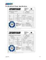
Page 46: ...Appendix 9 2 Certification Heater Specifications Figure 54 TUV SUD Certification Label 600 GTS Figure 55 TUV SUD Certification Label 600 GTS sub 40...

Page 47: ...Appendix 9 3 Electrical Schematics Figure 56 600 GTS sub 40 Electrical Schematic...

Page 48: ...Appendix 9 4 Figure 57 600 GTS Electrical Schematic...

Page 49: ...Appendix 9 5 Figure 58 HR2250 Electrical Schematic...

Page 50: ...Appendix 9 6 Figure 59 Trailer Wiring Schematic...

Page 51: ...Pros of Using HTF Preheater Using the HTF preheater according to recommendations will ensure a smooth start in all weather conditions thus providing a superior product to all users Allows the machine...

Page 52: ...reases heat exchanger service life Increases maintenance costs due to added stress on all components during cold startups In Conclusion Using the preheater as instructed in the manual will allow you t...

Page 53: ...Appendix Material Safety Data Sheets The Material Safety Data Sheets MSDS included with this manual have been provided by DRYAIR s suppliers 9 9...

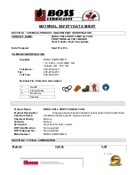
Page 54: ...x 403 279 2272 Toll Free 800 844 9457 National Fire Protection Association 1 Health 1 Flammability 0 Reactivity Special Product Name BOSS CHILL PROPYLENE GLYCOL Product Description Propylene Glycol ba...

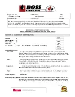
Page 55: ...entrations may cause irritation of nose and throat cause headache nausea or drowsiness Prolonged or repeated exposure may result in the absorption of potentially harmful amounts of material Skin A sin...

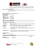
Page 56: ...rst Aid Procedures Eye Contact Flush eyes with large amounts of water for 15 minutes If irritation persists get medical attention Skin Contact Wash off in flowing water or shower Wash contaminated clo...

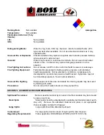
Page 57: ...uding positive pressure self contained breathing apparatus During emergency conditions overexposure to decomposition products may cause a health hazard Symptoms may not be immediately apparent Seek me...

Page 58: ...NIOSH MSHA for protection against organic vapors dust fumes and mists Protective Clothing Equipment Wear chemically protective gloves boots aprons and gauntlets to prevent prolonged or repeated skin c...

Page 59: ...r the major components product is practically non toxic to aquatic organisms Irritation Index Estimation of Irritation Species Not determined Environmental Fate Decomposes to carbon oxygen nitrogen an...

Page 60: ...subject to change and may differ from one location to another It is the buyer s responsibility to ensure that its activities comply with federal state or provincial and local laws The following speci...

Page 61: ...MATION GIVEN HEREIN IS GIVEN IN GOOD FAITH AND FROM SOURCES WE BELIEVE RELIABLE BUT NO WARRANTY EXPRESS OR IMPLIED REGARDING ITS CORRECTNESS IS MADE The conditions or methods of handling storage use a...

Page 62: ...duct is acceptable for use where there is possibility of incidental food contact and as a product for use in the immersion or spray freezing of wrapped meat and packaged poultry products We recommend...

Page 63: ...swallowing small amounts Chronic Exposure In rare cases repeated excessive exposure to propylene glycol may cause central nervous system effects 3 COMPOSITION INFORMATION ON INGREDIENTS Chemical natu...

Page 64: ...zards Container may rupture from gas generation in a fire situation Violent steam generation or eruption may occur upon application of direct water stream to hot liquids Advice for firefighters Fire F...

Page 65: ...g m3 50 ppm CA ON OEL TWAEV 10 mg m3 CA ON OEL TWA 155 mg m3 50 ppm CA ON OEL TWA 10 mg m3 Consult local authorities for recommended exposure limits Exposure controls Engineering controls Use local ex...

Page 66: ...to liquids Freezing point supercools Boiling point 760 mmHg 152 C Literature Flash point closed cup 104 C Pensky Martens Closed Cup ASTM D 93 based on major component Propylene glycol open cup Clevela...

Page 67: ...o Aldehydes Alcohols Ethers Organic acids 11 TOXICOLOGICAL INFORMATION Toxicological information on this product or its components appear in this section when such data is available Acute toxicity Acu...

Page 68: ...the major component s Did not cause birth defects or any other fetal effects in laboratory animals Reproductive toxicity For the major component s In animal studies did not interfere with reproduction...

Page 69: ...the most sensitive species tested LC50 Leuciscus idus Golden orfe static test 48 Hour 900 mg l Method Not Specified Persistence and degradability Propylene glycol Biodegradability Material is readily...

Page 70: ...posal practices must be in compliance with all Federal State Provincial and local laws and regulations Regulations may vary in different locations Waste characterizations and compliance with applicabl...

Page 71: ...y the CPR Hazardous Products Act Information WHMIS Classification This product is not a Controlled Product under WHMIS Canadian Domestic Substances List DSL DSL All substances contained in this produc...

Page 72: ...activities comply with all federal state provincial or local laws The information presented here pertains only to the product as shipped Since conditions for use of the product are not under the cont...

Reviews: