Setup/Operation (HR2250)
6-1
6. Setup/Operation (HR2250)
*DANGER! It is very important that you read and understand this section before
operating the hose reel. Failure to follow the procedures and cautions in this manual
could lead to injury and possible death!*
Manual Controls
The Hose Reel has a manual method of controlling the spool rotation
“UNLOAD/LOAD” and a general ON/OFF power switch.
*CAUTION! When NOT operating the reel, put the reel speed
toggle switch figure 39 (1-1) in the “Off” position to prevent
accidental activation and possible injury. When the hose reel is to
be left unsupervised, the power cord should be unplugged from the
power supply.*
Reel Power
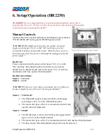
Power is present when the power switch
figure 39
(1-1) is in the
“On” position. By connecting the foot switch, you can load or
unload hose by depressing the foot switch
figure 39
(1-2) which is
momentary (will only operate when depressed).
Reel Direction Modes
Mode 1
- UNLOAD
Mode 2
– LOAD
*CAUTION! Take care not to allow your hands, feet or clothing to
become trapped by any of the reel’s moving mechanisms.*
Mode 1
– “UNLOAD”
•
The UNLOAD mode is achieved with the mode toggle
switch
figure 39
(1-2) in the UNLOAD position.
•
The foot switch
figure 40
(2-1) is momentary and will only
operate when it is depressed.
Mode 2- “LOAD”
•
The LOAD mode is achieved with the mode toggle switch
figure 39
(1-2) in the LOAD position.
•
The foot switch
figure 40
(2-1) is momentary and will only operate when depressed.
•
The hose must be directed manually into position on the hose reel.
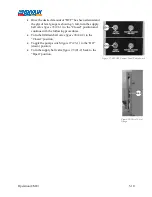
Figure 39-Power & Mode Toggle Switches
Figure 40-Foot Switch
Summary of Contents for 600 GTS Series
Page 2: ......
Page 47: ...Appendix 9 3 Electrical Schematics Figure 56 600 GTS sub 40 Electrical Schematic...
Page 48: ...Appendix 9 4 Figure 57 600 GTS Electrical Schematic...
Page 49: ...Appendix 9 5 Figure 58 HR2250 Electrical Schematic...
Page 50: ...Appendix 9 6 Figure 59 Trailer Wiring Schematic...

