DROPSA MaXtreme Operation And Maintenance Manual Download Page 11


11 

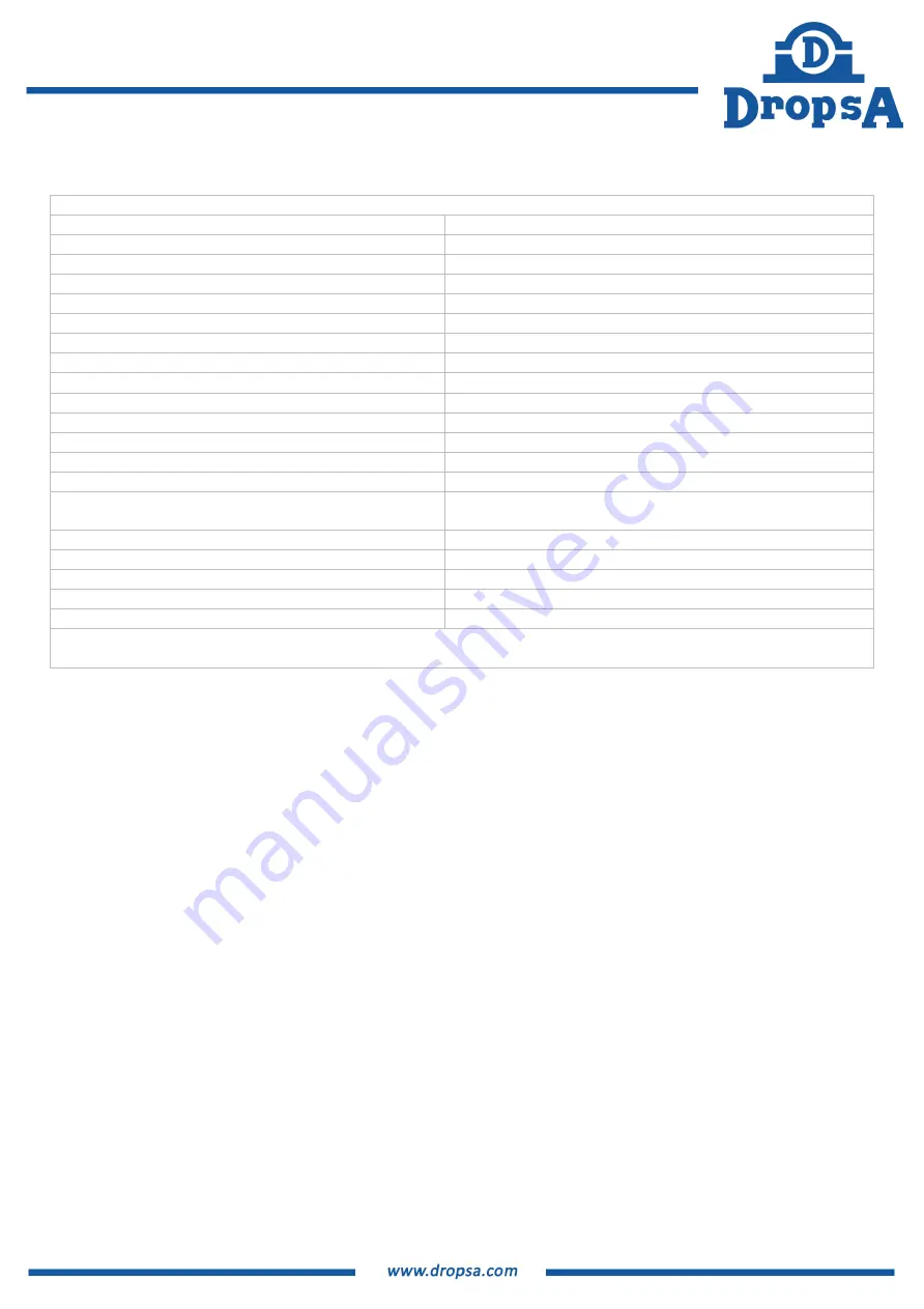
5. TECHNICAL CHARACTERISTICS 


Technical characteristics


*LP nozzle Air Supply:   

6 Bar (87 psi)


*LP nozzle air/outlet flow rate: 

35000 Nl/h (W/additional air) (1236 cfh) 6 Bar


*Oil Flow rate: 


220 ml/h (13.2 cu/h) 20°C


*HP nozzle Air Supply: 


20 Bar (290 psi) 


*HP nozzle air/outlet flow rate:


6500 Nl/h (229.5 cfh)


*Nozzle oil flow  HP: 


9.5 ml/h 

(0.6 cu/h) 20°C


Min. working diameter LP nozzle (6 bar) 

2 mm (7000 Nl/h) (247 cfh)


Minimum working diameter HP nozzle (20 bar) 

0.8 mm (3500 Nl/h) (123 cfh)


Reservoir capacity: 

2 litres (0.50 gallons)  

Air supply hose:  

Ø12mm.(0.47 in) 

Usage tube:  

Ø12 ÷ 16 mm (0.47 ÷ 0.6 in.)


Number of aerosol outlets:  

1~3 

Lubricant 

DropsA

 recommends 

MaXtreme

 OIL for the best results 

Degree of protection: 

IP 65 


Electro-pneumatic valve power supply: 
 (Optional) 

24VDC200mA  

Operating temperature 

0°C ÷ +60°C 

Storage temperature 

-10°C ÷ +80°C 

Noise (distance 1mt) 

70 dB “A” 

Escape valve: 

22 bar 

Reservoir pressure gauge

0~25 Bar


All the values on the technical characteristics refer to Ø12 in/out connections 
* The value is variable depending on the outlet Ø or the tool chosen for HP nozzle version


Summary of Contents for MaXtreme

Page 1: ...2006 42 MaXtreme Processing with a minimum quantity aerosol lubrication Operation and maintenance manual Original instructions DropsA products can be purchased at DropsA branches and authorised distributors go to www dropsa com contact or write to sales dropsa com ...

Page 2: ...INSTALLATION OF THE MACHINE 13 7 1 UNPACKING 13 7 2 INSTALLATION 13 7 2 2 COMPRESSED AIR CONNECTION 13 7 2 3 1 FIRST FILLING 14 7 2 3 2 SUBSEQUENT FILLINGS 14 7 3 PIPES AND NOZZLES 15 8 OPERATING INSTRUCTIONS 15 8 1 MAXTREME SETTINGS 15 8 2 START UP BASIC PRINCIPLES 15 8 3 INTERNAL LUBRICATION 16 8 5 ELECTRICAL CONNECTIONS MINIMUM LEVEL 18 8 6 PROBLEMS AND SOLUTIONS 18 9 MAINTENANCE PROCEDURES 19 ...

Page 3: ... particles in an ultra fine aerosol diameter below the micron that allow high performance machining The double vortex solution is a revolutionary system that allows minimal lubrication and superior internal or external near dry lubrication In fact for some applications the second nozzle optimised for higher pressures is designed to increase the aerosol flow directly on tools with minimum passage s...

Page 4: ...rsion Remote HP piloting from CNC by inserting an ON OFF solenoid valve OPERATING CONDITIONS VORTEX 1 VORTEX 2 EXTRA AIR AEROSOL DENSITY PRESSURE TANK ΔPress 1 2 NORMAL TOOLS ON OFF OFF NORMAL NORMAL ΔPress 2 BIG TOOLS ON OFF ON LOW LOW ΔPress 1 SMALL MEDIUM TOOLS ON ON OFF NORMAL HIGH NORMAL ΔPress 1 SMALL TOOLS OFF ON OFF HIGH HIGH AEROSOL FLOW AND CONSUMPTION DEAD ZONE NO AEROSOL ZONE HIGH PRES...

Page 5: ...ituation the pressure inside the tank will tend to increase thus closing the check valve 9 Increased pressure will facilitate the release of machining waste material ensuring continuous tool cooling lubrication Ref sheet 2 Page 6 There is no oil regulation on the HP circuit The oil can be filled from the port 16 or the valve 15 which also acts as an oil drain The max min oil level in the tank is d...

Page 6: ...6 Hydraulics diagram Vortex Operation LP Vortex HP operation from pneumatic pilot valve Scheme 1 Scheme 2 Piloting LP HP with solenoid valve Scheme 3 ...

Page 7: ... mandatory to use hearing protectors Hot surface danger Do not touch It is mandatory wear eye protection Danger container under pressure It is forbidden to switch off with water It is mandatory to ensure the ground connection Danger of crushing hands It is mandatory to disconnect the current Explosive area danger Protective glows must be worn Warnings table Warning Damage to Definition Consequence...

Page 8: ...f the equipment DropsA S p A declines any responsibility for damage to person or things deriving from the improper use of the equipment form the tampering of its safety devices or from the non observance of the safety rules at work WARNING It is necessary to read the Use and Maintenance Manual of the equipment to know the risks of use 3 1 Materials present on the system None of the materials used ...

Page 9: ...ng to the PED Directive and must be a non hazardous mixture according to agreements EC 1272 2008 GHS with the following physical characteristics Viscosity 50 cSt 40 Density 918 Kg m 3 15 C Flashpoint 250 C For the disposal of the oil strictly adhere to local provisions and the related MSDS Material Safety Datasheet DANGER The lubricant used in the lubrication circuits is a fluid that is flammable ...

Page 10: ...features CAUTION Before each intervention check the absence of residual pressures in each branch of the lubricant circuit After long periods of inactivity check the seal on all the parts subject to pressure Do not subject the fittings pipes and the parts under pressure to violent impact A damaged hose or fitting is DANGEROUS replace it ...

Page 11: ...le 20 bar 0 8 mm 3500 Nl h 123 cfh Reservoir capacity 2 litres 0 50 gallons Air supply hose Ø12mm 0 47 in Usage tube Ø12 16 mm 0 47 0 6 in Number of aerosol outlets 1 3 Lubricant DropsA recommends MaXtreme OIL for the best results Degree of protection IP 65 Electro pneumatic valve power supply Optional 24VDC200mA Operating temperature 0 C 60 C Storage temperature 10 C 80 C Noise distance 1mt 70 dB...

Page 12: ...nput air 20 bar HP circuit quick exhaust valve 20 bar Safety valve Pressure relief valve tank Network pressure regulator unit Tank pressure gauge Slide valve On Off High flow nozzle 6 bar Oil flow regulator Air inlet network Port of use free Solenoid valve optional Quick connect ø12 optional Filling port oil Oil level visual Oil drain oil load valve Flowmeter ...

Page 13: ...ll the equipment in the vicinity of the machine tool ensuring that it is a suitable environment for this type of equipment Strictly follow the following rules In order to avoid malfunctions always position the equipment vertically NEVER turn the equipment upside down For filling and control of the system place the equipment in an easily accessible environment NOTICE Place the equipment on the mach...

Page 14: ...d block the system In that case eliminate the residual pressure Ref par 9 1 and proceed as described in paragraph 7 2 3 1 FIRST FILLING UP WARNING During the filling operations always disconnect the system from the compressed air by acting on the manual sliding valve and on the multiplier supply pressure reducer by turning it fully counterclockwise When filling the tank never exceed the maximum B ...

Page 15: ...cularly the case when used with small tools with high rotational speed WARNING The equipment must operate according to the parameters indicated in the technical characteristics 8 OPERATING INSTRUCTIONS The same general procedures and precautions typical of the installation of traditional lubrication and cooling systems must be observed 8 1 MaXtreme SETTINGS Refer to the figure in paragraph 6 Air q...

Page 16: ...ubrication Ensure that there is no excessive bending or shrinkage diameter reduction of the piping in the lubrication line This would result in a deposit of lubricant in these areas preventing the aerosol from reaching the machining centre Make sure that aerosol mist comes out of the tool The workpiece must be positioned at a maximum distance of 40 mm 1 57 in from the outlet of the minimum lubrica...

Page 17: ...C NOTICE For optimal performance the use of a heater is recommended when used at temperatures 20 C TANK PRESSURE bar Oil flow rate cc h Airflow Nm3 h TANK PRESSURE bar TANK PRESSURE bar COMBINED AIR VORTEX OIL FLOW RATE Oil flow rate cc h Airflow Nm3 h Oil flow rate cc h Airflow Nm3 h HIGH AIR OIL FLOW RATE PRESS 20 BAR VORTEX 2 FLOW RATE AIR OIL NORMAL PRESSURE 6 BAR VORTEX 1 OIL FLOW RATE CC H A...

Page 18: ...Make sure that there is mains air and that all valves and pressure reducers are correctly set Faulty solenoid valve Contact service centre DropsA S p A Activating the working solenoid valve does not generate aerosols Faulty solenoid valve Contact service centre DropsA S p A The tank pressure is equal to the supply pressure Increase the air passage hole on the unit to be lubricated Oil missing Chec...

Page 19: ...ive Decree 81 2008 and in good condition in accordance with the prevailing regulation in order to prevent damage to personnel or parts of the machine 9 1 REMOVAL OF THE PRESSURE RESIDUE Refer to the figure in the paragraph 6 Remove mains pressure by acting on the on off slide valve Remove the mains pressure on any external accessory Open the quick exhaust valve on the head making sure that the pre...

Page 20: ...any other document must be destroyed 11 ORDER INFORMATION Accessories Part number Description 3155187 Solenoid valve for aerosol control 0295188 Air multiplier kit 0295189 On Off solenoid valve kit for high pressure circuit 0295272 On Off solenoid valve kit for low pressure circuit Consumable Products Part number Description 3226692 Maxtreme Oil 22 Lt 3226693 Maxtreme Oil 206 Lt 3226694 Maxtreme O...

Page 21: ...21 12 2 DOUBLE PNEUMATIC ELECTRIC CONTROL NOZZLE Dimensions in mm inches A 570 22 5 B 292 11 5 C 170 6 69 D 232 9 1 E 439 17 28 F 97 3 81 G 120 4 72 H 140 5 51 I 157 6 18 L TUBO ø12 NIPPLO G1 2 ...

Page 22: ... associated with pumping oils under pressure WARNING Verify the chemical compatibility of the materials with which the unit is built with the fluid you intend to pump A wrong choice could cause in addition to damaging units and pipes serious risks for people leakage of products that are irritating and harmful to health and for the environment Never exceed the maximum operating pressure value allow...

Page 23: ...that have been deemed acceptable are listed below CAUTION Low pressure oil splashes are possible during maintenance for this purpose maintenance activities must be carried out using suitable PPE Electrocution This can occur only in the event of serious negligence by the user who however is qualified Inappropriate Posture The correct overall dimensions and the installation methods are indicated in ...

Page 24: ...ages Reprints even of extracts are only permitted with the approval of DropsA S p A We reserve the right to implement technical modifications to the machine at any time in order to improve safety reliability function and design All descriptions and information in this product catalogue apply to the current state at the time it was created We reserve the right to change the contents of this documen...

Reviews: