


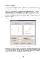
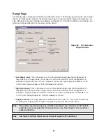


The compound linkage has two lever segments attached at one end to the pivot (the position sensor in
the SVI) and the other end to the valve stem pickup point. In order to compute the proper correction
curve, the user must enter the stroke length, first lever segment length (L1), second lever segment
length (L2), the distance from the pivot to the valve stem pickup (L3), and the valve position at horizon-
tal. Clicking the Compound button will compute the correction and display the curve.
Most linkages use a linkage with L3 equal to L1, i.e. the second lever arm is vertical when the first lever
arm are horizontal. The correction computation will correctly compute the correction curve when L3 is
not equal to L1. However, L3 must be greater than 0, which requires that the valve stem pickup not be
lined up with the pivot and that the pickup be on the same side of the pivot as the link between the first
and second lever segments.
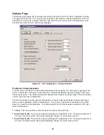
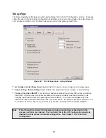
Local Button Lock
SVI comes with an optional local display and three explosion-proof pushbuttons for data entry. These
buttons can be used to perform basic SVI setup and operation without the need for ValVue or a hand-
held. Refer to Masoneilan SVI Instruction Manual for the functions of these buttons. It may be desir-
able after initial setup to "lock" the buttons so that the SVI parameters cannot be inadvertently changed
from the buttons. Several levels of locks are provided:
•
Allow Local Buttons:
Buttons on the SVI are fully enabled (level 3).
•
Lock Out Local Cal. - Config.:
The user may use the buttons to perform operations in normal
operating mode and manual mode, however he/she may not go to configure or calibrate mode
(level 2).
•
Lock Out Local Manual:
The user may examine variables in normal operating mode but may not put
the valve in manual operating mode and therefore cannot get to calibrate or configure modes
(level 1).
•
Lock Out All Buttons:
The buttons are disabled (level 0).
Bumpless Transfer
When this option is selected, returning from manual to normal operating mode is deferred until the cur-
rent valve position matches the input position.
While in manual mode, the valve position may be changed. It is possible that the normal position set-
point may also change during the time when SVI is in manual mode. If SVI is switched from manual to
normal mode, the valve will move toward the normal position setpoint and cause a bump that might be
unexpected. This option gives an operator a chance to adjust the normal position setpoint or manually
move valve position so they can match each other. When SVI is switch to normal mode, a smooth
resumption of control with little disturbance will result.
46
Note:
When using the SVI’s built-in process controller, do not select bumpless transfer
because this function is handled automatically by the process controller.


