


Chapter 17: Controller View
SVI has a built-in PID process controller, which can be enabled in configuration mode if the controller
option is purchased. The process controller is integrated with the SVI smart positioner to give a fast
response to process changes and disturbances, gain a tight control of process variable, and facilitate a
high level of loop monitoring functions.
ValVue provides interfaces for this controller to allow a user to monitor, manipulate, and tune the con-
troller. The interfaces for the controller include Controller Monitor window, Controller Parameters win-
dow and Process Trend window.
To setup a process controller, follow the following steps:
1.
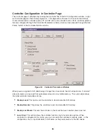
Turn the controller on in the Setup page and complete basic controller configuration in the Controller
page in the SVI Configuration window. Click OK to exit to the Manual Mode window (see Chapter
15 for details).
2.
Calibrate the controller in the SVI Calibration window and click OK to exit to the Manual Mode
window (see Chapter 16).
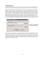
3.
Click the Controller View button to enter into the Controller Monitor window. Click the Set Param.
button to enter into the Controller Parameters window to finish controller configuration and set initial
PID parameters.
4.
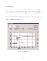
Tune the process control loop to refine PID parameters. The process trend graph can be used in
the tuning process while adjusting PID parameters.
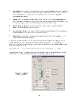
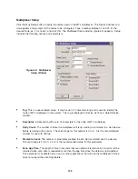
Controller Monitor
The Controller Monitor window (figure 57 shown on page 93) is a graphic interface for the SVI process
controller. Pressing the Controller View button, which is activated when the controller is enabled, in
either the Normal Operating or Manual Mode window will bring up the Controller Monitor window as
illustrated below.
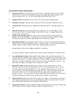
Display of Process Controller
On the monitor are the displays for the values of process variable, its setpoints and controller output,
both numerically and graphically. The process variable value as read from the secondary analog chan-
nel is displayed as a green bar. The setpoint is displayed as a solid white triangle. The display is
updated approximately every 2 seconds.
Current (mA) controller mode, remote automatic (R), local automatic (L) or manual (M), is also indicated
by a red light next to the corresponding R, L, or M button on the left top of the window.
The following describes variables related to the process controller:
•
Remote Setpoint:
For a non-ratio controller, this is the same as the measured setpoint, which is
read from the primary 4-20 mA input channel and scaled to engineering units. For a ratio
controller, remote setpoint is calculated from measured setpoint by
Remote Setpoint = Ratio Gain x Measured Se Ratio Bias
92


