background image

42

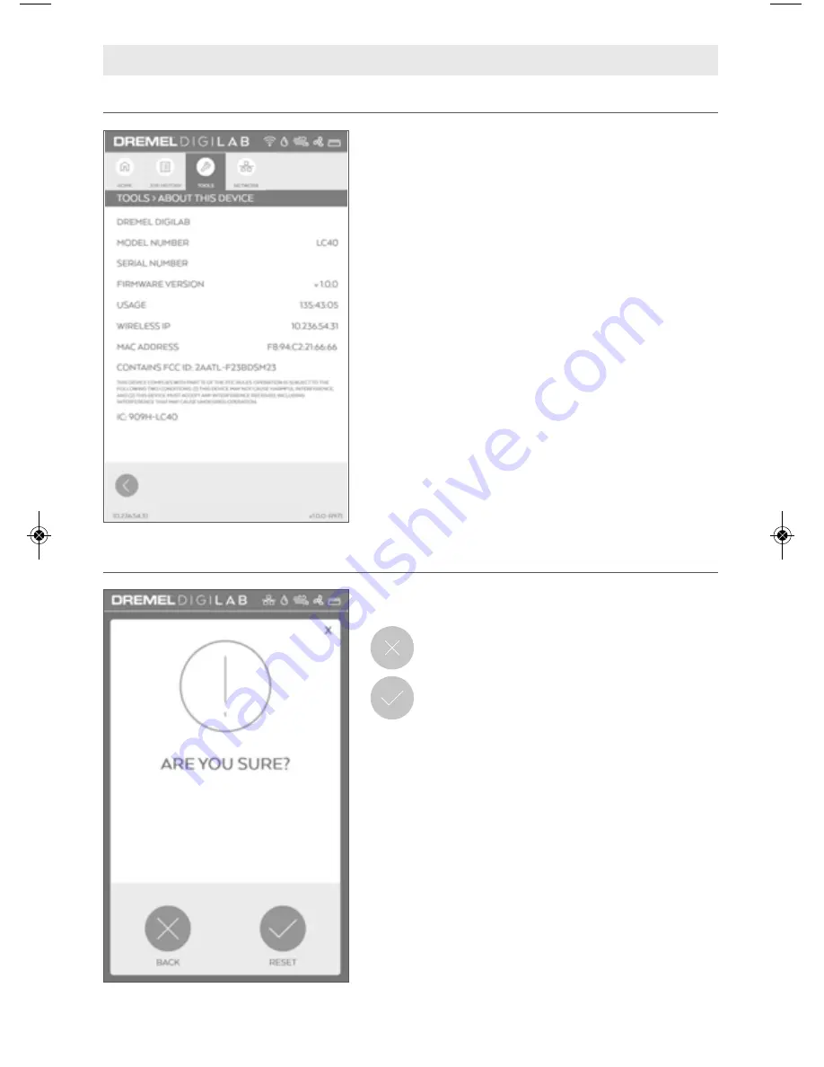
TOOLS > ABOUT THIS DEVICE

This  screen  displays  Dremel  LC40  Laser  Cutter

hardware and software information.

MODEL NUMBER — Displays unit model number.

SERIAL NUMBER — Displays unit serial number.

F I R M W A R E   N U M B E R —   D i s p l a y s   t h e   c u r r e n t l y

installed firmware version.

USAGE — Displays total hours of time that jobs have

been run.

W I R E D   I P —   D i s p l a y s   E t h e r n e t   I P   a d d r e s s ,   i f

connected.

WIRELESS  IP —  Displays  IP  address  assigned  by

wireless router.

MAC ADDRESS — Displays unique identifier assigned

to a network interface controller.

FCC ID — Displays FCC ID

IC ID — Displays IC ID

LCD TOUCH SCREEN

TOOLS > FACTORY RESET

This  screen  allows  for  verification  of  factory  reset

selection.

BACK

–  Tap  to  cancel  factory  reset  and

return to Tools > Menu Screen.

RESET

– Tap to perform factory reset.

NOTE  -  The  following  actions  occur  when  Factory  Reset  is

performed:

• EULA  screen  will  appear  on  next  power  up  and  needs  to  be

accepted.

• Country and Language selection will appear on next power cycle.

• Job history on the LCD software Interface will be cleared.

• Default  material  settings  will  be  restored  for  the  Laser  browser

interface software.

• User custom material settings will be cleared.

• Network configuration will be restored to default with all custom

settings cleared.

• Saved wireless network and password will be cleared.

• Ventilation  setting  will  revert  back  to  default  of  EXTERNAL

FILTRATION/VENTILATION SYSTEM.

DM 1600A01CX8 08-18 LC40 EN.qxp_LC40  8/17/18  10:32 AM  Page 42

Summary of Contents for DIGILAB LC40

Page 1: ...TANT READ BEFORE USING 1 844 4DRML3D 1 844 437 6533 www dremel com P O Box 081126 Racine WI 53408 1126 Dremel DIGILAB LC40 Laser Cutter Operating Safety Instructions Call Toll Free for Consumer Information Service Locations ...

Page 2: ...l Software 56 61 Tests Alignments 62 69 Mirror Alignment Overview 62 Tools Supplies Needed for Tests Alignments 62 4 Corner Mirror Alignment Test 63 64 Mirror Alignment Procedure 65 69 Tube Guard Removal 70 Operating the Dremel LC40 Laser Cutter 71 81 Prohibited Uses Restrictions 71 Create a Project 72 Maintenance 82 84 Troubleshooting 84 Shipping Storage 85 Serviceable Parts 86 Firmware and Open ...

Page 3: ...ers to interact with the laser cutter while it is operating Persons unfamiliar with the operation of the laser cutter may change its setup which may increase the risk of electric shock fire and or serious injury Electrical Safety Laser cutter plugs must match the outlet Never modify the plug in any way Do not use any adapter plugs with earthed grounded laser cutters Unmodified plugs and matching o...

Page 4: ...bris Clean the laser A build up of cutting and engraving residue and debris is dangerous and may increase the risk of fire Never look into the beam of the alignment laser Eye injury can result Never operate the alignment laser without the focus lens or other optical elements of laser cutter in place The unfocused beam may be reflected out of GENERAL SAFETY WARNINGS clothes jewellery or long hair c...

Page 5: ...rances could result in personal injury death and or property damage Wear proper personal protective equipment such as safety glasses protective clothing and work gloves when performing exhaust connections Failure to do so may result in personal injury Discontinue use and seek fresh air if respiratory or eye irritation occurs Ensure ventilation exhaust and or filtration systems are working accordin...

Page 6: ...le operating the laser This symbol designates that this tool is listed by Underwriters Laboratories to United States and Canadian Standards SAVE ALL WARNINGS AND INSTRUCTIONS FOR FUTURE REFERENCE ADDITIONAL SAFETY WARNINGS Use of controls or adjustments or performance of procedures other than those specified herein may result in hazardous radiation exposure Do not tap or scratch LCD screen with sh...

Page 7: ...out This Device screen page 42 for access to additional FCC IC compliance information FCC COMPLIANCE INFORMATION ON INTELLECTUAL PROPERTY The Dremel LC40 is intended for laser cutting engraving materials to create objects using digital files and digital designs that you create or own or have the right to use when you operate the Dremel LC40 When cutting engraving materials to create objects using ...

Page 8: ...2V DC 4 7 A OPERATING ENVIRONMENT Recommended Environmental Temperature 60 85 F 16 29 C Sturdy flat nonflammable and level workspace that holds weight of the Laser material and Hex Box For indoor use only SUPPORTED OPERATING SYSTEM AND SYSTEM SPECIFICATIONS Compatibility Mac PC Apple Mac OS X v10 9 or later Mavericks Microsoft Windows 10 Microsoft Windows 8 1 Microsoft Windows 7 SP1 Browser Compat...

Page 9: ...Y DREMEL LC40 LASER CUTTER HEX BOX CLEARANCE REQUIREMENTS SPECIFICATIONS X must be at least 26 660 mm when using onboard fan and at least 10 254 mm when using external booster fan See Exhaust Management section p 24 for details Y 6 152 mm min bend radius See Exhaust Management section p 24 for details ...

Page 10: ... PVC Found in many common products such as but not limited to flooring siding piping roofing membranes credit cards toys flexible tubing POM Delrin acetyl Rubber Styrofoam Wood that has been Coated Fumigated Pressure treated Stained MATERIAL USAGE Table 1 Dremel LC40 Laser Cutter Commonly Used Materials Acrylic Aluminum anodized Plywood Cork Cardboard Cotton fabric Denim fabric Felt wool Glass Lea...

Page 11: ...rication Resource Description Location Quick Start Guide Provides an illustrated walkthrough of how to un box the Dremel LC40 Laser Cutter and start a job Printed version is located in the box with the Dremel LC40 Laser Cutter It is also available on digilab dremel com support laser support Dremel LC40 Laser Cutter LCD Interface Provides step by step instructions for setting up the Dremel LC40 Las...

Page 12: ...mel LC40 Laser Cutter Honeycomb Plate An aluminum tray that rests on the bed and supports the work piece as it is cut and engraved Job A project that is sent to the laser for fabrication Laser Head An assembly of components including a mirror lens and cone which the laser passes through before making contact with the material LC40 Control Software The laser control software that is provided on the...

Page 13: ...the front or rear of the workspace INTRODUCTION Welcome to the world of Dremel Digilab Our mission is to mentor you through the digital fabrication process and share best practices for bringing your ideas to life Laser cutting and engraving are processes that will invoke experimentation and persistence The Dremel team is here to make your job easier with online tips documentation and live support ...

Page 14: ...l the project sample material and the Honeycomb Plate 2 Remove Instructional Manual Water Hoses Air Tube Screws Hex Box Cap Hex Keys Spacer Puck from box 2 3 Remove foam to reveal the Dremel LC40 Laser Cutter Use two people to lift Dremel LC40 Laser Cutter out of box by straps and place on workstation After the Dremel LC40 Laser Cutter has been taken out of the box hook straps to the Reusable Tote...

Page 15: ...ones de funcionamiento y seguridad Call Toll Free for Consumer Information Service Locations Pourobtenirdesinformationsetlesadressesdenoscentresdeserviceaprès vente appelezcenumérogratuit Llame gratis para obtener información para el consumidor y ubicaciones de servicio Operating Safety Instructions Ethernet Cable Water Hose 1 blue 1 clear Air Tube black 2 Hose Clamps Hex Box Connector Cord Hex Bo...

Page 16: ...Tube Guard 8 Honeycomb Plate 9 Gantry 10 Mirror 1 11 Beam Combiner Lens 12 Mirror 2 13 Laser Head a Mirror 3 b Focus Lens c Air Assist Nozzle d Laser Head Knob e Wide Angle Camera 14 Power Switch 15 Power Cord 16 Hex Box Power Outlet 17 Air Inlet 18 Exhaust Shroud 19 Water Outlet 20 Water Inlet Hex Box 21 Water Tank Cap 22 Water Tank 23 Power Inlet 24 Air Outlet 25 Water Outlet 26 Water Inlet ...

Page 17: ...17 GETTING TO KNOW YOUR DREMEL LC40 LASER CUTTER c e d b a 2 0 12 6 7 8 9 11 10 13 Fig 2 ...

Page 18: ...AU ENTRADA DE AGUA Hex Box 12V 23 24 25 22 21 26 GETTING TO KNOW YOUR LASER CUTTER AIR TUBE TUYAU À AIR TUBO DE AIRE Hex Box 12V 18 19 20 17 14 16 15 WATER OUT SORTIE D EAU SALIDA DE AGUA WATER IN ENTRÉE D EAU ENTRADA DE AGUA Fig 3 Fig 4 REAR VIEW OF DREMEL LC40 LASER CUTTER REAR VIEW OF HEX BOX ...

Page 19: ...emely fragile Be careful NOT to damage any part of the machine during this process Cut and Remove Zip Ties Fig 5 SETUP Observe all provided warnings and safety instructions prior to and when using the Dremel LC40 Laser Cutter Failure to do so may result in fire equipment damage property damage and or personal injury up to and including death Disconnect the plug from the power source before making ...

Page 20: ...d out of the way by hand if necessary The Honeycomb Plate sits flat at the bottom of the Dremel LC40 Laser Cutter There is a slight recess in the bed to help align the Honeycomb Plate Fig 6 Install Honeycomb Plate Fig 6 SETUP Remove the cap from the camera lens on the Laser Head Fig 7 Remove Camera Lens Cap Lens Cap Fig 7 Camera Recess in Laser Bed Recess in Laser Bed ...

Page 21: ...utlet fittings on the Dremel LC40 Laser Cutter and the Hex Box Fig 8 9 The fittings are labeled with colors to help identify the appropriate tubes Attach Water Hoses WATER IN ENTRÉE D EAU ENTRADA DE AGUA WATER OUT SORTIE D EAU SALIDA DE AGUA AIR TUBE TUYAU À AIR TUBO DE AIRE Hex Box 12V WATER OUT SORTIE D EAU SALIDA DE AGUA WATER IN ENTRÉE D EAU ENTRADA DE AGUA Clear Water Hose Blue Water Hose Blu...

Page 22: ... 10 11 Attach Air Tube AIR TUBE TUYAU À AIR TUBO DE AIRE WATER IN ENTRÉE D EAU ENTRADA DE AGUA WATER OUT SORTIE D EAU SALIDA DE AGUA Hex Box 12V Air Tube AIR TUBE TUYAU À AIR TUBO DE AIRE Hex Box 12V Air Tube SETUP Air Tube Fitting Air Tube Fitting Fig 10 Rear of Dremel LC40 Laser Cutter Fig 11 Rear of Hex Box Push the ends of the tubing onto the fittings until they are snug Correct Incorrect ...

Page 23: ...AIR TUBO DE AIRE Hex Box 12V Connector Cord SETUP Connector Fitting Connector Fitting Fig 12 Rear of Dremel LC40 Laser Cutter Fig 13 Rear of Hex Box Attach Exhaust Shroud Fig 14 Using a screwdriver attach the Exhaust Shroud to the back of the Dremel LC40 Laser Cutter Fig 14 Ensure that the Exhaust Shroud is flush and tight against the back surface of the Dremel LC40 Laser Cutter Attachment of the ...

Page 24: ...th Consult a qualified installer or service agency for information or assistance if installation of exhaust venting is beyond your skill level Improper installation adjustment alteration service maintenance or use can cause fire electric shock or other conditions which may cause personal injury property damage or even death Always use fire rated rigid or flexible metal or metalized ducting in the ...

Page 25: ... use location and operating parameters Always operate the Dremel LC40 Laser Cutter in a well ventilated area Installer of Dremel LC40 exhaust management system is responsible for complying with applicable codes and regulations including those for hazardous or noxious exhaust ventilation systems Exhaust Management Method Maximum Laser Fabrication Time in hours day hr day and hours week hr wk Home R...

Page 26: ...he exhaust opening using an Exhaust Vent Hood with a corrosion resistant screen or grille not provided Openings in the screen or grille should be between and and should be protected against local weather conditions Do not use louvered vent coverings as they can obstruct exhaust flow Install Exhaust Vent Hood according to manufacturer instructions Exhaust duct requirements Exhaust ducts shall be UL...

Page 27: ...requirements listed above Ensure that no more than 10 feet of exhaust duct is needed between the Dremel LC40 Laser Cutter and the discharge point 2 Select Exhaust Vent Hood that complies with exhaust discharge requirements listed above Install Exhaust Vent Hood according to the manufacturer s instructions and relevant building and fire codes 3 Attach the Exhaust Hose to the Dremel LC40 Laser Cutte...

Page 28: ...tion option on the Touch Screen during the Dremel LC40 Laser Cutter startup sequence The instructions provided below are for installing the materials provided by Dremel Consult manufacturer instructions for all other materials Items needed External Booster Fan flexible duct or smooth hard duct and elbows building code approved sealant or duct tape Exhaust Vent Hood 1 Identify an exhaust discharge ...

Page 29: ...Dremel LC40 Laser Cutter 1 10 ft Exhaust Hose 2 Hose Clamps Additional Items needed Building code approved sealant or duct tape filtration unit 1 Set up filtration unit according to manufacturer s instructions and relevant building and fire codes 2 Supplied 10 Exhaust Hose and Hose Clamps may be used if compatible with selected filtration unit 3 Seal all seams and connections with building code ap...

Page 30: ...erating GFCI reduces the risk of electrical shock Do not use laser cutter with extension cords The GFCI on the machine power cord will not prevent electrical shock from the extension cords The Dremel LC40 Laser Cutter is equipped with a GFCI unit mounted on the cord Fig 19 1 Press TEST button Red should disappear from the indicator window 2 Press and release RESET button Red should reappear in the...

Page 31: ... appear Tapping the Next button starts the hook up screens The screens review previous steps outlined in the Operating Safety Instructions After confirming all hoses and connections are correct stop at the Start Pump screen and follow the instructions below Get Started Locate the Power Switch at the back of the unit above the Power Cord and turn the Dremel LC40 Laser Cutter on Fig 20 Turn On the D...

Page 32: ...nk has stabilized at full 4 When the tank is full tap next button to proceed to the stop water pump screen 5 Stop the water pump by pressing the stop button on the Dremel LC40 Laser Cutter s LCD screen 6 Screw on the Hex Box Cap Fill Hex Box with Distilled Water AIR TUBE TUYAU À AIR TUBO DE AIRE WATER IN ENTRÉE D EAU ENTRADA DE AGUA WATER OUT SORTIE D EAU SALIDA DE AGUA Hex Box 12V Fig 21 Fill Lin...

Page 33: ...networks then enter password to connect the Dremel LC40 Laser Cutter 3 Open an internet browser window on the computer 4 Type in the IP number displayed at the bottom of the Dremel LC40 Laser Cutter s LCD screen into the browser s URL bar For a static IP address Connect to the network by assigning a persistent IP address that is assigned for the machine This address will be maintained permanently ...

Page 34: ...e the option to set a Static IP address using the LCD software interface Scenario 2 Connecting two or more Dremel LC40 Laser Cutters to a single computer using Ethernet connection A computer that has two or more Ethernet ports may connect to additional Dremel LC40 Laser Cutters Optional If the computer has an additional separate Ethernet Port or built in wireless the computer can access both the i...

Page 35: ... as the Internet through the Router The Dremel LC40 Laser Cutter gets access to the Internet from Router Note The Dremel LC40 Laser Cutter does have the option to set a Static IP address using the LCD software interface OR the Router can assign a Static IP address Scenario 4 Connecting two or more Dremel LC40 Laser Cutters to one or more computers using a router with wireless and or Ethernet Conne...

Page 36: ...trol Interface Information or additional action pertaining to selected menu item IP Address A unique number used to connect the Dremel LC40 Laser Cutter over a network to a web browser Firmware Version Displays the currently installed firmware version 1 2 3 4 5 Observe all provided warnings and safety instructions prior to and when using the Dremel LC40 Laser Cutter Failure to do so may result in ...

Page 37: ...uter via Ethernet Port The icon will disappear when there is no Ethernet connection Wireless Dremel LC40 Laser Cutter is connected to a computer or network router via wireless The icon will disappear either when there is no wireless connection or when the Ethernet icon is active When LC40 is connected with both Ethernet and Wireless only the Ethernet icon will display Water Cooling WHITE Cooling s...

Page 38: ...Enable the laser to fire for a short period to identify its location relative to the material Directional Arrows Moves the Laser Head in direction of arrow Laser Head Locked default Do not move the laser head by hand when locked Moving a locked laser head by hand may result in damage to the gantry system and or personal injury A closed lock icon indicates that the Laser Head is locked and can only...

Page 39: ... it will appear in the job history tab NAME the name of project job s within the Job History list RUN TIME required time to complete project 192 168 1 115 v1 0 0 LASER HOME JOG SPEED FAST TEST FIRE HOME JOB HISTORY TOOLS NETWORK Laser Head Unlocked An open lock icon indicates that the Laser Head can be moved by hand Note When Laser Head is unlocked the Directional Arrows and Speed virtual buttons ...

Page 40: ... Job selected from the list DELETE Delete files from the Job History list RUN PERIMETER Executes the run perimeter NEXT Changes the text to LOADING The Job will prepare to start Note If a job is rerun the system safety checklist will appear see Operation Screens page 54 ...

Page 41: ...splays service menu with customer service contact information TUTORIALS Displays short tutorials on operation of the laser TEST FILES Displays and allows execution of test files to verify proper operation of the laser UPDATE SERVICE Displays available service updates from Dremel Updates are pushed to the unit and cannot be requested The user has the option to accept or ignore the update LICENSES D...

Page 42: ...ORY RESET This screen allows for verification of factory reset selection BACK Tap to cancel factory reset and return to Tools Menu Screen RESET Tap to perform factory reset NOTE The following actions occur when Factory Reset is performed EULA screen will appear on next power up and needs to be accepted Country and Language selection will appear on next power cycle Job history on the LCD software I...

Page 43: ...F VENTILATION Displays a sub menu screen where ventilation type can be selected PRIME WATER PUMP Displays a sub menu with water pump controls TOOLS SETTINGS LCD TOUCH SCREEN TOOLS SETTINGS LANGUAGE This screen displays and allows selection of different languages Note Choosing the language on this screen does not set the software language on the computer only the LCD warning screens are affected ...

Page 44: ...an external fume ventilation system To assure proper removal of fumes produced during operation of Dremel LC40 Laser Cutter the ventilation selection must match the actual fume extraction set up Dremel LC40 must be set up according to instructions provided in the Exhaust Management chapter of the Setup section beginning on page 24 to assure proper ventilation ONBOARD FAN Select when only the vent ...

Page 45: ...R PUMP This screen provides control to start the water pump during priming of the laser cooling system START Starts the coolant pump This screen provides control to stop the water pump during priming of the laser cooling system STOP Stops the pump ...

Page 46: ...is screen provides access to available tutorial FOCUS LASER HEAD Instructions for adjusting the Laser Head to focus the laser beam on the work piece surface MACHINE SETUP Instructions for the initial setup of Dremel LC40 OTHER Instructions for cleaning of the mirrors and lens TOOLS TUTORIALS ...

Page 47: ...47 LCD TOUCH SCREEN TOOLS TUTORIALS Sequence of screens stepping through JOB PREP Sequence of screens stepping through HOOK UP ...

Page 48: ...C40 Laser Cutter Test Files CUT TEST BOX 1 thru CUT TEST BOX 12 are used to identify optimized cut and score settings Test Files ENGRAVE TEST are used to identify optimized engrave settings Recommended material size for tests 12 x20 TOOLS TEST FILES Preview the test file This sample screen illustrates how the option to run a test file can be selected NEXT To start running the job ...

Page 49: ... software updates LAST CONNECTION TIME Shows how long ago the last update service connection was made If unit is actively connected to update service then the LAST CONNECTION TIME will not be shown If an update is available an UPDATE AVAILABLE screen and UPDATE PENDING screen will be shown The update prompt which appears on the Home menu screen allows a user the option of accepting the update or d...

Page 50: ...ion menu Available options allow connection or disconnection from the wireless network and set up a static IP address WIRELESS Setup or modify a wireless local area network connection for the Dremel LC40 Laser Cutter to connect to 000 000 000 STATIC IP Setup the Dremel LC40 Laser Cutter to use a Static IP address or default to a DHCP Dynamic Host Configuration Protocol address IP address ...

Page 51: ...ted by the Dremel LC40 Laser Cutter Selecting an available network will start the connection process Wireless network signal strength indicator TOUCH SCREEN This screen displays the password prompt that appears when a password protected wireless network is selected ...

Page 52: ...is made DONE Return to Network menu screen NETWORK WIRELESS UNABLE TO CONNECT ACCEPT RETRY This screen displays a notification that appears when connection to the wireless network is unsuccessful RETRY Allows adjustment of the network information and an attempt to connecting again ACCEPT Return to Network screen ...

Page 53: ...r a wireless or a wired LAN network STATIC IP Allows selection of Static IP adress DHCP Allows selection of Dynamic Host Configuration Protocol address IP address Values displayed on IP Address Netmask and Gateway are ignored but saved for future use AUTO DNS Allows the Dremel LC40 Laser Cutter to use the domain name system server as determined by the network router MANUAL Allows for inputting a s...

Page 54: ... inputs that must be completed before a job can be started TOUCH SCREEN CHECKLIST SCREEN ERRORS DETECTED Displays errors detected in systems of the Dremel LC40 Laser Cutter while it is preparing to start a job The status bar will also display red icons for system or systems where errors were found Link to a trouble shooting tutorial related to the system where an error was found ...

Page 55: ... from the same place STOP Cancel the current job OPERATION SCREENS TOUCH SCREEN If all icons at the top are white then items in the checklist should be green Manual checks that can be completed after the work piece is placed in the workspace and Laser Head adjusted using the spacer puck To start the job the Lid must be closed and the Start Button rapidly pressed twice ...

Page 56: ... Software The LC40 Control Software will link a web browser with the Dremel LC40 Laser Cutter using the IP address found at the bottom of the LCD home screen on the local connection Wireless or Ethernet Menu Bar includes the following menu options File Edit shown when a project is opened and Help Tool Bar includes the following tools Import Undo Redo Auto Array Material Time Options Run Perimeter ...

Page 57: ...cal the object that is highlighted ROTATE RIGHT select to rotate right the object that is highlighted ROTATE LEFT select to rotate left the object that is highlighted SELECT ALL select to select all DESELECT ALL select to deselect all C HELP ABOUT YOUR LASER select to see more details about your Dremel LC40 Laser Cutter MANUAL select to access the Dremel LC40 Laser Cutter Operating Safety Instruct...

Page 58: ...optimal application CAPTURE Use import capture to access the camera capture feature This can be used to capture a picture of the actual work piece on the Honeycomb Plate and place the image into the background of the LC40 Control Software workspace Additionally the camera can take a picture of a sketch placed on the Honeycomb Plate and transform that sketch into a file which can be engraved or cut...

Page 59: ...aterial manufacturer to determine the response of any work material to extreme heat burning fire hazard to prevent hazards Click to select a material from the list of Dremel provided commonly used materials or choose more to add delete edit the list of favorite materials Use the star to denote a default material that will be saved and used for all jobs until changed The settings that are populated...

Page 60: ...creen once ready to send Print Settings box Cut HEAT Adjust how quickly the laser is firing or how much heat is generated on the surface of the work piece Turning up the heat will cause charring for materials like wood or paper but will create a glossy edge for a material like acrylic SPEED Adjust how quickly the Laser Head moves Slowing the Laser Head down allows it to cut deeper into the work pi...

Page 61: ...deep the laser will go into the work piece Increasing the depth will remove more material so that a noticeable void is felt when touching the work piece creating almost a 3D effect Reducing the depth will keep the surface of the work piece relatively flat or even SPEED Adjust how quickly the Laser Head moves Slowing the Laser Head down will generally make the engraving darker or deeper while incre...

Page 62: ...rs when Gantry is manually moved while the motors are locked Air Assist Nozzle is displaced Laser Tube is replaced mirrors lens are replaced or during shipping Alignment of the mirrors is necessary to ensure that the Laser Beam remains properly aligned with the Focus Lens as the Laser Head moves to all four corners of the workspace After alignment the Laser Beam should be centered on the Focus Len...

Page 63: ...ns to the work piece Note Dremel LC40 Laser Cutter Lid must be closed for each test fire Materials needed Thermal paper supplied 2 5mm hex wrench supplied 1 Open the Lid 2 Place the thermal paper Take a small piece of thermal paper approximately the same size as the face of the lens and place it over the focus lens under Mirror 3 Fig 30 3 Press the paper down with a finger so that a circle appears...

Page 64: ... in step 5 Observe which mark is from which location 8 Check Results With the fourth corner test fire complete open the Lid and observe the thermal tape The four spots should overlap each other Fig 32 If the spots do not overlap as shown perform the Mirror Alignment Procedure on page 65 9 Once the spots are aligned place thermal paper under the Air Assist Nozzle on the Honeycomb Plate at all four ...

Page 65: ...motor connector while holding the Gantry e Replace the Tube Guard using great care not to damage any wires or the Laser Tube 4 Rerun the four corners mirror alignment test to see if further alignment is necessary Step 2 Preparation Prepare your tools and workspace 1 Power On Dremel LC40 Laser Cutter The machine must be powered on to continue this procedure Allow the machine time to boot up the tou...

Page 66: ...en The Fire button will appear after all of the system checks have passed Press the button one time and observe where the spot lands on the thermal paper From here forward called Test Fire 6 The spot should be centered on the Beam Combiner Lens Remove the thermal paper 7 Repeat steps 2 5 at Mirror 1 Fig 34 8 The spot should be centered at Mirror 1 and not clipped by the Beam Combiner Lens If it is...

Page 67: ... the red dot exactly over the burn mark at position B on Mirror 2 c If the red beam is not hitting the mirror at all it may be necessary to use a larger card or paper to determine where the red dot is d Go slowly and do not overtighten screws Small turns of the screws are required to move the beam at long distances e It is best to align the red dot at the furthest distances B and C to avoid small ...

Page 68: ...tment of Mirror 2 will negate the alignment of B C 1 Open the Lid 2 Place Thermal Paper as before on Mirror 3 3 Move the Gantry to Position C 4 Note that it is possible that Mirror 2 can be adjusted far enough out of range and potentially damage the rubber of Mirror 3 when the Dremel LC40 Laser Cutter is fired Look for the Alignment Laser It should give an indication of where the Laser Beam is poi...

Page 69: ...ap Test Fire without removing the paper as it may be necessary to mark this spot This is Spot L1 7 Tweak the red dot to match the spot on the paper Due to the reflections of all of the mirrors the red dot may not move with the same screw turns as it did previously 8 Adjust Mirror 3 continuing to test fire until the spot is nearly perfectly centered a Note do not overly tighten Mirror 3 b In rare i...

Page 70: ...tube guard The LED lights may be damaged by contact with tube guard edges LASER TUBE GUARD REMOVAL For some tasks the Tube Guard requires removal so that components can be accessed Examples are Gantry alignment motor connector adjustment fan cleaning and Laser Tube replacement If removal is required follow the steps below 1 Move the Gantry to it s furthest forward point Fig 39 2 Loose the 3 captiv...

Page 71: ...all hazardous substances or reduce their concentration to acceptable levels so never use materials that are prohibited see Table 2 Always check https digilab dremel com support faq for the latest material information OPERATING THE LASER CUTTER Observe all provided warnings and safety instructions prior to and when using the Dremel LC40 Laser Cutter Failure to do so may result in fire equipment dam...

Page 72: ...wise inappropriate for the environment or iii In violation of another s intellectual property rights For example the Dremel LC40 Laser Cutter will not be used to reproduce material that is subject to copyright patent or trademark protection iv Used as a structural component The use of parts made must be thoroughly evaluated by a competent professional prior to being included in any structure or v ...

Page 73: ...ting a file or files The files are available from 3 sources A Creating files in a graphics program B Importing previously created files C Using the camera capture feature Most files are created through the use of software such as CorelDRAW Adobe Illustrator or other graphic software Depending on the software and how the file was created a project is developed to run a job that will allow the Dreme...

Page 74: ...nize different colors in vector files and allow the application of different settings based on those colors For a single image file the same print settings need to be applied to the entire file For example to engrave the dark area in this image in a dark shade and the white in this image in a light shade it is best to export the dark area and the white text and circle outline as two separate files...

Page 75: ...e or corner etc or if it is a small piece of material In order to use this function Option 1 1 In the LC40 Control Software go to IMPORT menu Click on IMPORT CAPTURE 2 Follow the on screen instructions Place the material onto the center of the Honeycomb Plate and close the Lid Click NEXT 3 The LED Lights in the laser will flash off and a red dot will appear If the red dot is not on top of the work...

Page 76: ...race a drawing or sketch For this application it s best to use a black marker on white paper Steps 1 4 are the same as in the previous capture method Follow steps 1 4 on previous page 5 Drag a box around the area of the sketch that will be turned into a laser file Choose to make the selection sensitivity higher or lower by switching between the 3 threshold options and click next 6 Choose whether t...

Page 77: ...he screen 4 Adjust print settings as needed If the settings are changed in this box they will override Dremel recommended settings until a new material is selected The top right side of the print settings box will unlock more precise setting options Review job and job execution order to make sure the desired result 5 Send the job to the Laser If you would like to save a job to your computer to rep...

Page 78: ...e laser on the Honeycomb Plate Fig 43 Always place the work piece on the Honeycomb Plate for cutting jobs For engraving or scoring thicker pieces of material the Honeycomb Plate can be removed and the work piece placed directly placed on the surface that supports the Honeycomb Plate If it is an irregularly shaped work piece such as a cylinder place the work piece anywhere on the laser bed and use ...

Page 79: ...lens Loosening the knob frees up the focus lens to move up and down 3 Raise the Laser Head and place the Spacer Puck between the Laser Head and the work piece 4 Let the Laser Head rest on the Spacer Puck and tighten the Laser Head Knob to fix the Laser Head in place 5 Remove the Spacer Puck Note If the work piece to be engraved is too thick to fit in the laser with the Honeycomb Plate remove the H...

Page 80: ...eed to be fixed before beginning the job Touch the next to the appropriate line item for help diagnosing and correcting each error Refer to Touch Screen information starting on page 36 for additional information OPERATING THE LASER CUTTER Step 4 Send the Job to the Laser Close the Dremel LC40 Laser Cutter Lid The Run Perimeter feature on the LCD laser screen or in the LC40 Control Software can be ...

Page 81: ...o the laser beam may cause ignition of combustible materials and start a fire Always use the air assist as recommended by the manufacturer especially while cutting Cutting movements are relatively slow and apply an extremely large amount of heat to the work piece Avoid the build up of heat in order to reduce the risk of fire Do not operate when access door is open An open door can lead to stray ra...

Page 82: ...p the swab or lens wipe in the lens cleaner solution use a gentle circular motion to clean the lens surface 3 Use dry swabs or wipes to gently dry the lens surface 4 Reassemble the focus lens in the lens holder Procedure for cleaning mirrors Never remove the mirrors for cleaning Take extra caution to not move the orientation of the mirrors as this will affect laser beam alignment and would require...

Page 83: ...hould be cleaned at least monthly Cleaning the enclosure Wipe down the external surfaces of the enclosure with a soft cotton towel Use light pressure to avoid scratching the surface Cleaning the glass Lid and side covers Use glass cleaner and a soft towel to clean the Lid The plastic side covers should only be cleaned with glass cleaner or a mild soap solution Use a soft towel and light pressure D...

Page 84: ...a Clean the exhaust fan and Exhaust Shroud After prolonged use the fan performance can diminish due to dust build up on the fan blades and Exhaust Shroud If the laser has been used for a lot of woodcutting cleaning will need to be done more frequently Debris can stick to any surface in its path If fan noise or vibration is detected a cleaning is required Disconnect the exhaust duct from the Exhaus...

Page 85: ...y system Secure the Gantry with plastic ties to minimize any movement of the Gantry during transportation 10 Return the Hex Box to its original shipping location inside the Dremel LC40 Laser Cutter enclosure If it cannot be placed inside it must be secured to the pallet outside of the Dremel LC40 Laser Cutter 11 When shipping the Dremel LC40 Laser Cutter the unit must be secured to a pallet to pre...

Page 86: ...e available for service Observe all provided warnings and safety instructions prior to and when using the Dremel LC40 Laser Cutter Failure to do so may result in fire equipment damage property damage and or personal injury up to and including death Have your laser cutter serviced by a qualified repair person using only identical replacement parts This will ensure that the safety of the laser cutte...

Page 87: ...x 081126 Racine WI USA 53408 1126 The request should include i the name of the Dremel product ii the serial number if applicable iii the software version if applicable iv your name v your company name if applicable and vi your return mailing and email address if available We may charge you a nominal fee to cover the cost of the physical media and distribution Send the request i within three 3 year...

Page 88: ...ection shows that the problem was caused by problems with material or workmanship within the limitations of the warranty Dremel will repair or replace the product free of charge and return the product prepaid Repairs made necessary by normal wear or abuse or repair for products outside of the warranty period if they can be made will be charged at regular factory prices DISCLAIMER OF IMPLIED WARRAN...

Reviews: