476
Issue date: 17 November 2006
16 of 80
8.5
As the diaphragm deflects, it then presses against the main hinged lever of the balanced piston
unit resulting in the release of the positive pressure ‘off’ mechanism.
8.6
Increasing deflection of the diaphragm, during inhalation, pivots the cam of the main lever against
the secondary lever.
8.7
The secondary lever then pivots and presses against the end cap of the piston – moving the
piston axially against the conical spring – lifting the piston cone from its seating and releasing air
from the LDV into the wearer’s face mask.
8.8
A compression spring attached to the front cover of the LDV acts on the diaphragm, then the
pivot levers and the conical compression spring, lifting the sealing cone and maintaining a
positive pressure (above ambient) inside the face mask.
8.9
When the wearer stops inhaling and then begins to exhale, the diaphragm, the pivot levers and
the sealing cone all retract.
8.10
This cycle repeats as the wearer begins to inhale again.
8.11
The LDV is designed to maintain positive pressure inside the mask.
Use in hi - expansion foam
8.12
For use in hi-expansion foam the outer rubber casing should be released from the body of the
LDV prior to use, see appendix 1 for details.
9
Pneumatic system
First stage pressure reducer
9.1
Leading from the first stage pressure reducer are the:
•
High pressure hose to electronic monitoring unit (EMU).
•
Low pressure warning whistle (LPWW).
•
Medium pressure hose to in-line connection with LDV hose.
•
Medium pressure hose to second person connection.
•
Cylinder connection.
9.2
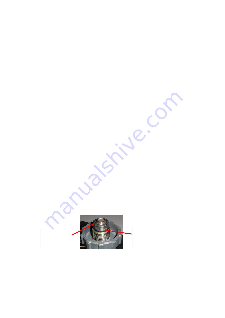
An additional compression ‘O’ ring located between the hand wheel and the flange of the high
pressure (HP) connector, functions as an anti-vibration device.
9.3
This feature prevents the inadvertent loosening of the hand wheel from the port of the cylinder
valve, during storage conditions involving vibration, when the system is not pressurised.
9.4
The reducer has two outlet ports, one providing high pressure air to the EMU, and the other
providing medium pressure air only to a ‘Y’ piece which supplies both the LDV and second
person connection. The LPWW is situated in the middle port of the reducer body.
LFB image 245568
Cylinder
connection
‘O’ ring
Anti-vibration
‘O’ ring


