6
Exit Device Operators 630/750/79E/RT/E7900 Series/ Generation E-730 PK3677_T
10-18
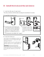
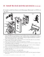
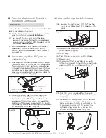
4.1 Insert the slotted end of the spindle (D) into the outside housing until it locks, at the correct posi-
tion for the exit device (see the document named ‘’ spindle position’’). The spindle can be removed
by pulling on it, and re-inserted if oriented incorrectly. Choose a spindle that engages by 1/8” mini-
mum in the exit device chassis and that it is not too long to bottom-out against the exit device
mechanism to jam the lock assembly, once it is tightened down.
4.2 Place the outside housing (B) on the door. (with gasket (C) if required)
4.3 Attach Adaptor Plate (E) to the lock (B) using 3 Flat Head screw (F)(12-24nc).
4.4 Attach the Exit Device chassis (G) to the Adaptor Plate (E) using 2 screws or 4 screws (H) depend-
ing on the Exit Device. For Detex only, use 2 or 4 Flat washers (Q).
4.5 Make sure the lock and the Exit Device are well aligned and then tighten screws.
4.6 Follow the manufacturer’s instructions to complete the installation of the exit device and the
appropriate strike.
H
Q
D
C
B
G
Q
H
E
F
Fig. 3
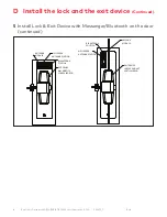
4 Install Lock & Exit Device on the door
D Install the lock and the exit device


