Exit Device Operators 630/750/79E/RT/E7900 Series/ Generation E-730 PK3677_T
10-18
5
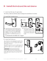
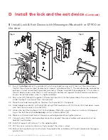
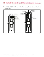
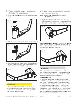
Three AA batteries should already be installed in the
battery holder (J). Insert the battery holder into the
outside housing and secure it using the 6-32 X 3/8”
spanner drive screw (K).
For de E7900 series lock, insert the 4 AA batteries into
the battery holder (J). Insert the battery holder into
the enclosure and secure it using the supplied screw
(K).
CAUTION
WARNING
IMPORTANT
If the lock makes a continuous buzzing noise or the
red LED lights continuously, reset the electronics by
removing the battery holder for ten seconds, then
reinsert it.
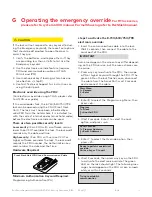
* For Mechanical Override Models refer to page 12.
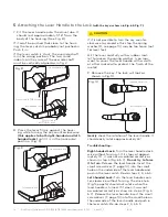
Assemble the lever on the outside housing,
in the horizontal rest position appropriate
to the handing of the door as shown. Simply
push the lever onto the tube until it clicks
in place. If more force is required to engage
the handle, use a rubber mallet. Test the
attachment of the handle by pulling smartly
on it.
For mortise exit devices, install the mortise according to the manufacturer’s instructions.
A
1 Install the Mortise (if applicable)
2 Install the Outside Lever
3 Install the Batteries
Access Hole
cutaway view
J
J
K
K
K
D Install the lock and the exit device
The lever is field reversible. If
the handing is incorrect, insert
a small pick or flat screwdriver
in the hole in the hub as shown.
Gently pry back the spring clip
inside the hub, and remove the
handle.
B


