


1835-067-A-9-18
1
Table of Contents continued on next page
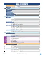
TABLE OF CONTENTS
Important
Notices
FCC - United States, DOC - Canada
Glossary
General
Information
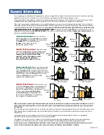
Installation Guidelines and Safety Information
SECTION 1 - INSTALLATION
1.1 General Installation
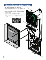
1.2 Remove Components from Enclosure
1.3 Enclosure Dimensions
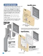
1.4 Install Enclosure
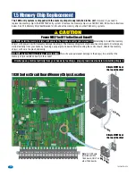
1.5 Memory Chip Replacement
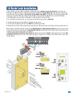
1.6 Postal Lock Installation
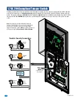
1.7 UL 294 Compliant Tamper Switch
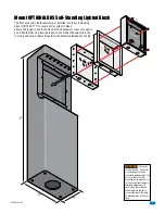
1.8 OPTIONAL Internal Card Reader Installation
1.9 OPTIONAL Camera Kit Installation
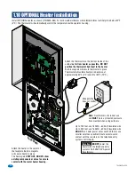
1.10 OPTIONAL Heater Installation
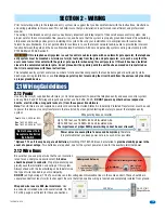
SECTION 2 - WIRING
2.1 Wiring Guidelines
2.1.1
Power
2.1.2
Wire
Runs
2.1.3
Grounding
2.1.4
Surge
Suppression
2.1.5
Expansion Boards and Elevator Control
2.1.6
Ferrite
Filter
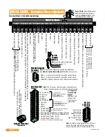
2.2 Terminal Descriptions
2.3 Telephone Entry System Wiring
2.3.1
ALL telephone Entry Systems - No Tracker Expansion Boards
2.3.2
Hardwired Tracker Expansion Boards
2.3.3
Tracker Expansion Boards using Wireless Communication
2.4 PC (DATA) and VOICE (PHONE) Connection Options
2.4.1
DoorKing Cellular Network Connection - Voice/Data Transfer
2.4.2a DoorKing VoIP/RS-232 Control Box - Voice/Data Transfer
2.4.2b DoorKing VoIP Internet Connection - Voice/Data Transfer
2.4.2c Third Party VoIP Internet Connection - Voice/Data Transfer
2.4.2d DoorKing TCP/IP Converter Mounting Position
2.4.3a DoorKing IM Server Modem Connection - Voice/Data Transfer
2.4.3b Dial-Up Phone Modem Connection - Voice/Data Transfer
2.5 Direct Connection to PC Options - Data Transfer ONLY
2.5.1
RS-232 Direct Connection - Data Transfer ONLY
2.5.2
RS-422/USB Direct Connection to PC - Data Transfer ONLY
2.5.3
TCP/IP Converter Direct Connection to PC - Data Transfer ONLY
SECTION 3 - PROGRAMMING
3.1 General Programming Information
3.1.1
Programming from a PC
3.1.2
Programming from the Telephone Entry System Keypad
3.1.3
System Memory Chip Identification
3.2 Setup Telephone Entry System for PC Programming
3.2.1
Master
Code
3.2.2
Number of Area Codes Allowed
3.2.3
Call-Up Operation when Interfacing with DoorKing 1816 or 1820 Systems
3.2.4
Resident Elevator Button Relay Time
3.2.5
“Tone Open” Sound ON or OFF
3.2.6
RS-232 Speed Setting
3.2.7
Switch Input Feature
3.2.8
Elevator Control Feature
3.2.9
Single or Multiple Systems
3.2.10 DKS Data over IP Phone Number or System ID Number
3.2.11 Re-Program Memory Size, with/without Cards and Anti-Pass Back
3.2.12 LIVE Transaction Viewing from a PC - ON or OFF
Overview for System Keypad Programming
3.3 General Programming using the System Keypad
3.3.1
Relay Strike Time
3.3.2
Talk
Time
3.3.3
Tone Open Numbers
3.3.4
Switch Input Relay(s) Activation
3.3.5
Touch-Tone / Rotary-Dial
3.3.6
Rotary-Dial 9 Relay(s) Activation
3.4 Programming Letters, Numbers and Messages
3.4.1
Programming Letters, Numbers from Keypad
3.4.2
Programming the User Message - 1835 System ONLY
3.4.3
Programming the Instruction Message - 1835 System ONLY
3.4.4
Programming the User Message - 1837 System ONLY
3.4.5
Programming the Instruction Message - 1837 System ONLY
3
4
5
5
6
7
8-9
10
11
12
13
13
14
15
15
15
15
16
16
16
16
17
18
18
19
20
21
21
22
22
22
23
23
23
24
24
24
24
25
25
25
25
26
26
26
27
27
27
27
28
28
28
28
29
29
30
31
32
32
32
33
33
34
34
35
35
36
37
38
39
Quick Quide Terminal Descriptions
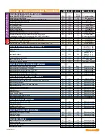
Overview for System Keypad Programming
NOT programmable from
Software.
System Keypad
Programming ONL
Y
System Keypad Programming
when NOT using a PC
Quick Guide - 1
Quick Guide - 2