


1835-067-A-9-18
14
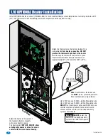
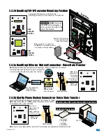
Install OPTIONAL heater as shown (P/N 2600-584). For cold weather climates where temperatures routinely drop below 40°F
(4°C). The thermostat will automatically control the temperature inside operator housing.
1.10 OPTIONAL Heater Installation
DOOR
KIN
G
149
1-010
BACKLI
TE
CUT
OFF
CONTRAS
T
8 LI
NE
DISPLA
Y
DOORKING 1892-010
SIN
GLE
LINE
DISPLA
Y
16A
C
16AC
BAT
1N
O
1N
C
1C
2RY
2C
A
Z
IMC
5VDC
IMD
SPKR
COM
MIC
PSW
CGND
PHONE
P1
P2
HOT
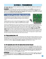
Important:
DO NOT
power the
heater with the telephone entry
system’s 16.5 VAC 20 VA power
transformers.
12 V
AC
40 V
A
Output
Wire polarity
does not matter
Attach the heater in the center of
the faceplate. Built-in magnets
will secure heater in place.
The heater gets
VERY HOT, DO NOT allow
existing components or wires to come in
contact with the metal heater housing.
Faceplate
Attach the thermostat on the bottom inside of the
cabinet
as far from heater as possible. DO NOT
position the thermostat right next to the heater.
Built-in magnets will secure thermostat in place.
Thermostat will automatically turn heater on at
approximately 40°F (4°C) and off at 55°F (12°C).
Note:
Transformer is for indoor use
and
MUST
be in a protected enclosure
from weather when using outdoors.
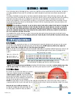
Up to 100 feet, use 18 AWG - 600 volt insulated wire.
Up to 200 feet, use 16 AWG - 600 volt insulated wire.
DO NOT
run heater power wires over 200 feet or use
smaller wire than specified. Route wires to avoid
contact with the resistors on the telephone entry
system control board.