


1835-067-A-9-18
20
NC
NO
NO NC
C
ON
ELEVATOR
12
34
5
6
7
8
9
10
11
12
13
14
1
2
3
OFF
KEYPAD
MASTER
CODE
16AC
16AC
BAT
1NO
1NC
1C
2RY
2C
A
Z
IMC
5VDC
IMD
R
14
13
12
11
6
5
4
3
2
1
DOORKING
2363-010
PAIRED
ON
OFF
0
F
E
D
C
B
A
9
8
7
6
5
4
3
2
1
0
F
E
D
C
B
A
9
8
7
6
5
4
3
2
1
RF RANGE
CH
NET
ID
RCVD
ALLOW
DENY
STATUS
SYNC LOST
SYNC REVD
HEARTBEAT
DISPLAY
OFF/ON
RESET
RF
STAT STRENGTH
DOORKING
2361-010
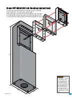
2361 Wireless
Baseboard Kit
2361 Wireless
2361 Wireless
Baseboard Kit
Baseboard Kit
Auxiliary
Terminal
Connection
Power
Transformer
Required.
Connect to
#1 and #2.
Antenna
Required
Antenna
Required
100 ft max
Relay 2 Connection Required.
Relay 1
Relay 2
Relay 0
4-Pin Terminal
Main Terminal
Relay 0
Main
Door/Gate
Wireless T
racker Board Addresses 3-10
Wireless T
racker Board Addresses 11-18
Relay 2 Jumper
Set to NO
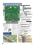
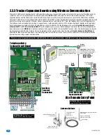
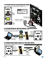
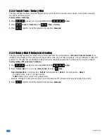
The model 2358 Tracker Expansion Board (sold separately) allows you to expand the number of remote entry points that the telephone entry
system can control. One tracker expansion board is required for
EACH
remote entry point. Communicate wirelessly between the tracker
expansion boards and the 1830 Series controller without having to run wiring from each remote access point to the 1830 Series controller.
The model 1489 wireless tracker expansion board kit and the model 2361 wireless baseboard kit (each sold separately) plugged onto to circuit
boards for wireless communication. Wireless tracker expansion boards can be up to 100 ft from the telephone entry system (approximate).
This distance can be extended by using longer range antennas (sold separately) and/or a 2372 wireless dual band repeater (sold separately).
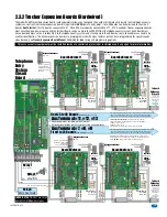
Each tracker expansion board must have a board address set on it to identify it to the telephone entry system.
Board addresses 3-10 will
activate RELAY 2
and
11-18 will activate RELAY 1
on the telephone entry system. Board addresses can be set the same for multiple boards
(zone addresses) when
MORE
than 8 boards need to activate a specific RELAY (24 boards MAX for each relay). The tracker expansion boards
are pre-programmed with many features but can be programmed for specific needs when desired (See
Tracker Expansion Board Manual
2358-065 for
ALL
programming options). See DoorKing’s web site and the instruction sheets with the wireless kits for complete installation
information when using wireless communication.
2.3.3 Tracker Expansion Boards using Wireless Communication
Telephone Entry
System Circuit Board
At a Remote Entry Point
34
33
32
31
30
29
28
27
26
25
24
23
22
21
14
15
16
17
18
19
20
13
12
11
10
9
8
7
6
5
4
3
2
1
ON
1
0
BOARD ADDRESS
0
9
8
7
6
5
4
3
2
1
NC
OUTPUT
RELAY
NO
NC
ALARM
RELAY
NO
NC
AUX
RELAY
NO
ENT
RESET
2358-010
RF
DATA
RF
SECURE
RF
STATUS
CODE
SENT
CODE
GOOD
CODE
BAD
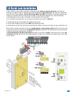
Lock Power
UL listed
Board Power
UL listed
#33 & #34
16 VAC
20 VA
Wiegand Card
Reader
#6 - #9
Ground #32
Door Lock
or Gate
Operator
#25 & #26
Connect card
reader using
4 conductor,
stranded with
overall shield.
18, 20, 22 or
24 gauge.
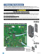
IMPORTANT NOTE:
ONLY use circuit
board 2361-010
Rev E
or higher.
IMPORTANT NOTE:
ONLY use circuit
board 2358-010
Rev L
or higher.
Board
Address
Setting
2358-010 Tracker
Expansion Board
PROGRAM
0
F
E
D
C
B
A
9
8
7
6
5
4
3
2
1
0
F
E
D
C
B
A
9
8
7
6
5
4
3
2
1
RF ID
RF CH
RF
STRENGTH
RF
LOST
POWER
RF
SYNC
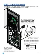
1489-010
RF RANGE
1489
Wireless
Kit
1489
1489
Wireless
Wireless
Kit
Kit
Antenna Note:
This wireless system
works best when the antennas are in
direct-line-of-sight with each other, in
free air as high as possible above the
ground.
Antenna Options
Externally Mounted
Antenna Kit
P/N 1514-075
Range is approximately
500 ft direct-line-of-sight.
Cabinet Mounted Longer Range Antenna
P/N 1514-002
Range is approximately
200 ft direct-line-of-sight.
Range is approximately
500 ft direct-line-of-sight.
Wireless Dual Band Repeater
P/N 2372-080
Signal Note:
Channel Number
and RF ID Number must match
on 2361 wireless baseboard kit
and ALL 1489 wireless kits.
0
F
E
D
C
B
A
9
8
7
6
5
4
3
2 1
CH
NET
ID
0
F
E
D
C
B
A
9
8
7
6
5
4
3
2 1
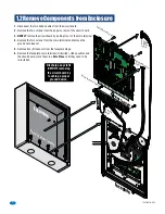
This access control equipment must be installed inside of a controlled, protected or restricted area. See page 3 for more information.
8 LINE
DISPLAY