background image

  DONATI SOLLEVAMENTI S.r.l. - Via Quasimodo,17 - 20025 Legnano (MI) - Tel. 0331 14811 - E: [email protected] 


44


6.4 Setting the brake on the motors on “DGT” drive units and endcarriages 


The motor on the “DGT” drive units and endcarriages is a self-braking type with axial shifting 
of the rotor. 


Braking  is  mechanic  and  is  provided  by  a  conical  brake  block,  equipped with a brake lining 
that  is  integral  with  the  rotor,  and  which,  in  the  absence  of  power,  is  thrust  by  a  spring  in 
contact with the braking surface on the brake cover. 


The brake linings do not contain asbestos, and are subject to wear depending on the intensity 
of work operations. 


Wear on the brake linings increases the amount of play between the lining and brake block; 
this  leads  to  a  progressive  loss  of  brake  torque  and  consequent  brake  skidding  and 
lengthening of brake spaces; proper maintenance on the brake is consequently essential. 


Adjust the brake torque as follows: 
A)  On  the  outside,  adjust  the  brake  torque  in  the  case  of  modest  wear  or  to  modify  preset 

torque settings. 

B) On  the  inside,  restore  the  brake  play  in  the  case  of  heavy  wear  on  the  brake  lining, 

increasing the motor shaft axial stroke > 1 mm. 


Adjustments on the brake on “DGT” drive units or endcarriages: 

A)  Externally set the brake torque 
B) Internally restoring the brake play 

 
WARNING!  The  use  of  a  safety  harness  is  mandatory  when  these  operations 

are conducted above ground level.


To  make  adjustments  on  the  brake  on 

“DGT”  drive  units 

or

  endcarriages

, whether externally adjusting the 

brake  torque 

A)

,  or  internally  restoring  the  brake  play 

B)

,  the  following 

PRELIMINARY  OPERATIONS 

are 

required

1.  Cut off power to the 

“DGT” drive units 

or

 endcarriages

2.  Get to the work area above ground level in safety; 
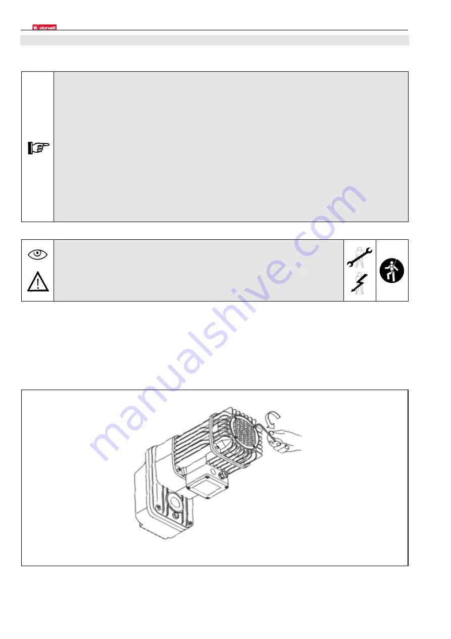
3.  Operating above ground level, remove the plastic grid (aerator), unscrewing the four screws completely, as 

shown in fig. 16. 


fig. 16 

Summary of Contents for DGT Series

Page 1: ...Drive UNITS FOR CRANES DGT Wheel Groups DGP Offset Geared Motors Endcarriages for Single girder and Double girder Bridge Cranes OPERATING MANUAL INSTALLATION USE MAINTENANCE KMAN19MG00...

Page 2: ...rations 11 2 3 6 Classification of DGT series drive units 3 SAFETY AND ACCIDENT PREVENTION MEASURES 12 3 1 Operator qualifications 12 3 2 General safety norms and regulations 13 3 3 Safety symbols and...

Page 3: ...6 MAINTENANCE 34 6 1 Safety precautions 34 6 2 Qualifications for maintenance personnel 36 6 3 Maintenance program 39 6 3 1 Daily and periodic maintenance 39 6 3 2 Maintenance frequency and deadlines...

Page 4: ...conservation If this operating should go missing or become damaged a replacement copy must be ordered directly from the manufacturer citing the code of this present operating manual The manufacturer m...

Page 5: ...to consider proposals for improvements so as to render this manual more responsive to the needs of users 1 4 Conformity to norms and regulations The components illustrated in this publication have bee...

Page 6: ...ill trained personnel So as to avail itself of the warranty as outlined in the certificate below the buyer must meticulously observe the prescriptions indicated in this operating manual specifically...

Page 7: ...ssembled to one other in relation to the user s requirements allow for the fast and economical realization of multiple standard and special configurations DONATI drive units are configured in 6 produc...

Page 8: ...lindrical high resistance steel gears featuring spiral toothing thermically treated entirely supported on ball bearings Sized to resist a lifetime of stress and wear in accordance to the pertinent ISO...

Page 9: ...rs guarantee accurate alignments control over high running speeds easy installation and maintenance 2 2 2 The range of endcarraiges The range of endcarriages for bridge cranes are designed in 6 produc...

Page 10: ...DONATI SOLLEVAMENTI S r l Via Quasimodo 17 20025 Legnano MI Tel 0331 14811 E dvo info donaticranes com 10 2 2 3 Components on travelling beams...

Page 11: ...he special waterproof paintwork finish adopted for electro mechanical parts swinging reducer and self braking drive motor obtained using an electrostatic process and the complete sealing of parts guar...

Page 12: ...ust also carefully observe all safety norms and regulations contained in this section of the operating manual in order to prevent potentially dangerous situations 3 1 Operator qualifications The table...

Page 13: ...asures specifically checking that the DGT drive units and or endcarriages have been set in stop mode no power or movement and in a stationary position disabled power cut off subjected to preventive me...

Page 14: ...uthorized personnel is forbidden WARNING SYMBOLS USED TO INDICATE OBLIGATIONS SYMBOL MEANING CONSULT THE MANUAL Consult the manual when this symbol appears preceding or within an indication instructio...

Page 15: ...Beams and or Wheels Ascertain that the rail wheel contact area is 2 7 m above the walking area For quotas 2 7 m enact special technical measures RISKS DURING MAINTENANCE DANGER RISK CAUTION WARNING OB...

Page 16: ...t the maximum travelling speed fig 3 2 Limit switches fig 4 a Electrical rotating shaft cross type when included equipped with sensitive micro switches which by activating the auxiliary circuit limit...

Page 17: ...and address specific weight of the motoreducer type serial number and code of the motor year of manufacture typical electrical specifications for the motor power absorption etc CE marking for the foll...

Page 18: ...ting manual comprises the Manufacturer s Declaration Annexe IIB The packaging if part of the shipment is in good condition and does not present damages In case of damage or missing parts notify the sh...

Page 19: ...a transverse bar of suitable diameter and a lifting accessory slinging the group using two chains or straps fig 7 The wheel groups weight less than 30 kg and as such can be handled manually 2 DGP off...

Page 20: ...nt are whole and that no parts and or accessories are missing Promptly notify the manufacturer of any damage or missing parts To store the materials follow the instructions outlined at section 4 5 1 S...

Page 21: ...JR EN 10027 and applicable regulations To assemble the beams incorporating the DGT drive units using an electric welding process be sure to respect the tolerances prescribed by ISO regulation 8306 88...

Page 22: ...n the wheel 7 4 Fasten the motoreducer 5 to the reaction arm 1 using the screw and nut 8 and inserting the rings 9 according to the correct sequence illustrated in the diagrams fig 11a and 11b and the...

Page 23: ...eel group Combination of DGT wheel groups with DGP offset gearmotors valid for both left and right operation Size mm DGP offset gearmotors Size 1 DGP offset gearmotors Size 2 3 200 4 250 Assembly diag...

Page 24: ...hose on the beam 2 2 Insert the screws 3 taking care to maintain the nuts and rings 4 on the outside i e on the plate 1 3 Screw on and set the nuts 4 without tightening them to allow the insertion of...

Page 25: ...the sliding units corresponds to the power voltage available 2 Verify the suitability and correct operation of the electrical system and grounding 3 Perform the electrical connections on the motor te...

Page 26: ...ur in the corresponding directions If the direction of the movements does not correspond to the required function immediately stop the manoeuvre and invert the connection of two of the phase connectio...

Page 27: ...ation alarm button if available verify the forward reverse sliding function in the case of movements at two speeds verify their operability check the operation of the motor brakes in their forward rev...

Page 28: ...protect all materials using barriers and hygroscopic salts Demarcate and cordon off the material storage areas 4 5 2 Resetting up the units after storage Before operating the DGT drive units and endc...

Page 29: ...food products or substances which can come into direct contact with parts on the DGT drive units and endcarriages or their lubricants loads whose static and or chemical physical configuration or bala...

Page 30: ...ges in maximum safety conditions For operations in areas not sufficiently lit operators must be equipped with a supplementary lighting system illuminating shadowy areas that can prevent or reduce visi...

Page 31: ...nerate dangerous load oscillations with risks of collisions or violent impacts between the DGT drive units or endcarriages and the endstroke mechanical stops Operate with attention and diligence keepi...

Page 32: ...drive units and endcarriages are positioned at a height of 2 7 m from the flooring i e such as to ensure that the operator will not interfere with moving elements wheels girders If this is not possib...

Page 33: ...e g pulling or dragging objects NEVER collide or impact load bearing structures machinery or installations with the DGT drive units and endcarriages NEVER leave the DGT drive units and endcarriages ex...

Page 34: ...RNING and DANGER every time a procedure is requested which can entail a risk of damage or injury WARNING notes precede operations which unless correctly performed can cause damage to the DGT drive uni...

Page 35: ...ke certain that a suitable ground connection exists and that it responds to ordinances in force Failure to provide a ground connection for electrical equipment can cause serious damage to personnel Be...

Page 36: ...the DGT drive units or endcarriages Qualifications requested qualified for work operations in relation to specific operative and environmental conditions Mechanical maintenance personnel Typical main...

Page 37: ...g as an industrial electrician with specialization and experience in maintenance on industrial lifting and handling systems Electromechanical maintenance personnel Operators who possess specifications...

Page 38: ...acity to organize measures capable of restoring proper performance to the DGT drive units or endcarriages capacity to draw up a summary of maintenance interventions Qualifications requested complete t...

Page 39: ...tenance operations that can be performed directly by the operator making use of the machine on which the DGT drive units or endcarriages are assembled or by specially qualified personnel as outlined i...

Page 40: ...ntenance checks Page Daily Monthly Quarterly Annualy Controls Inspections Tests General visual checks Verify proper operation General visual checks Verify wear Annual tests 55 Drive motors Load tests...

Page 41: ...eck to make certain the brake unlocks correctly with each intervention and the rotor does not remain braked and or chaffing is detected With a nominal load control braking spaces times and effectivene...

Page 42: ...re in perfect condition repairing any damage found is required The reaction arms on the swinging reducers and hinged brackets and pins are subject to wear as moving and oscillating elements under ongo...

Page 43: ...s and or conductors that appear broken cut peeled or eroded Never carry out hasty repairs 6 3 4 Cleaning and lubrication DGT drive units or endcarriages must be thoroughly cleaned every three months i...

Page 44: ...brake spaces proper maintenance on the brake is consequently essential Adjust the brake torque as follows A On the outside adjust the brake torque in the case of modest wear or to modify preset torque...

Page 45: ...e head screw the spring thrust is at its minimum setting and consequently the brake torque is also at a minimum 2 Reset the hexagonal concave head centre screw with the desired washers and tighten sec...

Page 46: ...ke block of 1 mm 5 Draw the brake block in towards the ring nut matching up the boreholes 6 Reset the three screws into their original housings on the ring nut fastening them onto the block fig 23 7 R...

Page 47: ...rness textile fabric sling fastened loop like onto the connection area between the motor and swinging reducer fig 25 Disassembling the DGP offset gearmotor fig 26 1 Cut off power to the DGT drive unit...

Page 48: ...ation with respect to the flooring and available spaces dimensions and weight of the parts to be replaced 6 6 1 Replacing the brake on the motors on DGT drive units and endcarriages To replace the mot...

Page 49: ...ing harness Fig 31 It is advisable to replace all the wheels even if some of them appear in good condition To replace the wheels proceed as follows Fig 32 1 For a power wheel disassemble the offset ge...

Page 50: ...n out brake The driving operation won t stop at the end of the stroke worn out brake limit stroke operation The reducer is excessively noisy lack of lubricant incorrect overly intense operation unsuit...

Page 51: ...urnt out due to high start up frequencies insufficient protection replace the fuse check contactor power cable rewind the motor and ensure better protection check the control device Motor doesn t star...

Page 52: ...rials Do not attempt to re use parts or components on the DGT drive units or endcarriages which can appear still whole once they have been declared as no longer suitable through controls and or part r...

Page 53: ...42 CE must mandatorily accompany lifting equipment for which DGT units or sliding beams have been incorporated In addition to all activities regarding the working life and usage of the DGT units or e...

Reviews: