16
SectIon 6 lP gaS reQuIrementS
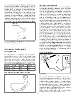
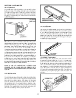
The LP gas pressure to the refrigerator should be 11 inch-
es water column with half of all BTU’s of the RV turned
on. With all other appliances off, the pressure to the re-
frigerator should not exceed 12 inches water column. To
check the gas pressure when the refrigerator is operating,
there is a pressure test port below the solenoid valve as-
sembly.
SectIon 7 lP gaS comPonentS
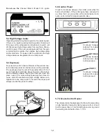
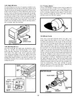
7.1 manual gas Shutoff Valve
The manual shutoff valve is a non-serviceable part. The
valve is part of the solenoid valve assembly. It is very rare
to have problems with the manual shutoff or the solenoid
assemblies. If you have checked gas pressure and it is
low, check pressure at input line to refer. If pressure is 11
inches at input and low at the pressure test port, change
solenoid valve assembly. The valve is not opening all the
way.
DO NOT use a flame to check for gas leaks.
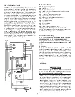
7.2 Orifice
The Dometic orifice is a brass alloy with a man-made ruby
pressed in the center that has been laser-beam drilled in
a spiral pattern. The orifice is cleaned by using an alcohol
based solvent. Soak the orifice for approximately 1 hour
and allow to air dry. Don’t insert anything in the center of
the orifice because it will harm the man-made ruby. Do
not use an air nozzle to blow thru the orifice as the ruby
could be moved. Never over or under size the orifice on a
Dometic refrigerator. The cooling unit is designed to work
with a predetermined amount of heat and modifying the
orifice size will decrease cooling. If there is a lack of cool
-
ing on gas operation, verify the orifice is the proper size
per the chart.
MODEL
JET SIZE
RM3762
#58
RM3962
#58
Always check the parts list with the model and product
number to assure the right jet size.
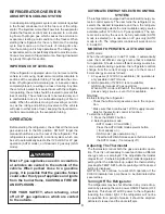
teStIng lP gaS Safety SHutoff
The gas safety shutoff must be tested after the refrigera-
tor is connected to the LP gas supply.
To test the gas safety shutoff, proceed as follows:
1. Start the refrigerator according to the instructions, and
switch to GAS mode.
2. Check that the gas flame is lit and the GAS mode indi
-
cator lamp is on.
3. Close the manual gas shutoff valve at the back of the
refrigerator.
4. Wait for six to seven minutes for unit to go into flame
failure after three tries. The CHECK indicator lamp should
be on and the GAS mode indicator lamp should be off.
5. Remove protection cover from burner and open the
manual gas shutoff valve. Do not change any button posi-
tions on the control panel. Apply a non-corrosive commer-
cial bubble solution to the burner jet orifice.
6. No bubbles should appear at the opening of the burner
jet orifice. The presence of bubbles indicates a defective
gas safety shutoff, and service is required.
7. If no bubbles were present at the burner jet orifice, it
should be rinsed with fresh water. Be careful not to dam-
age the burner jet orifice. Replace cover and press the
main power ON/OFF button (1) OFF and back ON. Nor-
mal operation of the burner should return. Allow the burn-
er to operate for a minimum of five minutes.
do not use a wire or pin when cleaning the burner
jet as damage can occur to the precision opening.
this can cause damage to the refrigerator or create
a fire hazard.
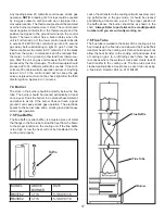
7.3 thermocouple
The Thermocouple is a component that extends over
the burner assembly so its tip is in the path of the flame.
During normal gas operation, the thermocouple should
produce 25 to 35 millivolts when connected to the lower
circuit board.
Summary of Contents for RM3962
Page 15: ...14 RM3762 RM3962...
Page 20: ...19 Typical Two Side Wall Vent Application Always Refer To Vent Instructions 3308666 xxx...
Page 23: ...22...
Page 28: ...27...
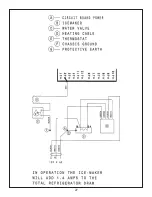
Page 29: ...28 ICE MAKER TYPICAL WIRING DIAGRAM...
Page 33: ...32...


