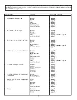
background image

9

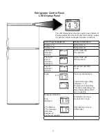
description of operating modes

to Shut off the refrigerator

The  refrigerator  may  be  shut  off  while  in  any  mode  of 

operation  by  pressing  the  main  power  ON/OFF  button 

to the OFF position. This shuts off all DC power to the 

control system including the interior light.

limp mode

This control system contains a feature where it will contin-

ue to operate the cooling system in event of a failure of a 

major operating component. If the power modules cannot 

communicate, the control system will revert to full AUTO 

operation selecting the best energy source available with 

AC first and GAS second priority. The temperature setting 

will  be  maintained  at  mid-position.  If  the  control  cannot 

read the temperature sensor, then the control will run the 

cooling unit continuously at the energy source available. 

The refrigerator will continue to operate in this mode in-

definitely or until a new sensor is installed and the system 

is reset. 

auto mode

When  operating  in  the  AUTO  mode,  the  AUTO  mode 

indicator dot is lit. The control system will automatically 

select  between AC  and  GAS  operation  with AC  having 

priority over GAS. If the control system is operating with 

AC energy and it then becomes unavailable, the system 

will automatically switch to GAS. As soon as AC becomes 

available again the control will switch back to AC opera-

tion. 

gas operation

 (120 volts AC is not available): The 

control  system  will  activate  the  ignition  system  and  will 

make  three  attempts  to  light  the  burner  for  a  period  of 

approximately 45 seconds with two minutes rest (purge) 

interval. If unsuccessful, LP will be flashing (the message 

alternates between LP and the temperature) in the dis-

play. To restart an ignition attempt with LP flashing in the 

display turn unit off, wait a few seconds and turn back on. 

The control system will attempt a new ignition sequence. 

If 120 volts AC becomes available while LP is flashing, the 

refrigerator will operate on AC but the LP flashing will not 

turn off until the main power ON/OFF button is pressed to 

the OFF then ON position.

this is an energized circuit.  Shock can occur 

if not tested properly.  testing is to be done 

by a qualified service technician.

When operating in the GAS mode, the AUTO indication 

dot will be off and the LP indication dot is lit. This mode 

provides LP gas operation only. The control system will 

activate the ignition system and will make three attempts 

to light the burner for a period of approximately 45 sec-

onds with two minutes (purge) interval after each trial. If 

unsuccessful,  the  display  will  flash  LP.  To  restart  GAS

operation, press the main power ON/OFF button to the 

OFF  and  then  ON  position.  The  control  system  will  at-

tempt a new ignition sequence. If the refrigerator has not 

been used for a long time or the LP tanks have just been 

refilled, air may be trapped in the supply lines. To purge 

the air from the lines may require resetting the main power 

ON/OFF button three or four times. If repeated attempts 

fail to start the LP gas operation, check to make sure that 

the  LP  gas  supply  tanks  are  not  empty  and  all  manual 

shutoff valves in the lines are turned on.

gaS mode

low ambient control

In colder weather, the temperature inside the absorption 

refrigerator lower box tends to hold the temperature inside 

for a very much longer period of time, with very long pe-

riods in between ON/OFF cycling of the heat source; this 

is OK for any food product inside the refrigerator cabinet, 

but is not OK for the freezer compartment (if it happens to 

have perishable product inside). Because of the long time 

in  between  cycling  ON/OFF,  there  is  a  chance  that  the 

temperature may rise above freezing in the freezer com-

partment, resulting in food spoilage. This is why we have

a low ambient control. If it so happens that the tempera-

ture  in  the  refrigerator  has  satisfied  the  thermostat  set

-

ting, and the CUT-OUT threshold has been reached, the 

refrigerator  cycles  OFF.  If  the  temperature  remains  at 

lower than the CUT-IN threshold for 35 minutes or longer, 

the LAC output will be activated; this output, typically, is 

connected to the interior lamp situated inside the refrig-

erator compartment. The warmth generated by the lamp 

slowly raises the temperature inside the refrigerator cabi-

net to the CUT-IN threshold; when CUT-IN is achieved, 

the refrigerator cycles back ON again. At this point, the 

LAC  output  is  de-activated,  and  the  interior  lamp  turns 

OFF. The refrigerator will now assume normal operation, 

and will continue to cool until thermostat is satisfied once 

more. If it should so happen that CUT-IN is not achieved  

again within 35 minutes, the LAC process will be initiated 

once more (and any time thereafter) as required.

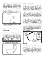
SectIon 2 ac Voltage

ac Voltage reQuIrementS

The refrigerator is a 120 volt AC, 60 Hz appliance. The 

proper  operating  range  is  100  to  132  volts.  If  voltage 

drops  below  100  volts,  cooling  efficiency  will  decrease 

with voltage decrease. Check the AC volts at the recepta-

cle where the refrigerator is attached. If voltage is outside 

of the proper operating range, correct the power source 

problem.

Summary of Contents for RM3962

Page 1: ...RM 3962 USA SERVICE OFFICE Dometic Corporation 2320 Industrial Parkway Elkhart IN 46516 574 294 2511 CANADA Dometic Distribution 46 Zatonski Unit 3 Brantford Ontario CANADA N3T 5L8 519 720 9578 Form N...

Page 2: ...dicates a potentially hazard ous situation which if not avoided may result in minor or moderate injury When used without the safety alert symbol indicates a potentially hazardous situation which if no...

Page 3: ...10 SECTION 5 DC COMPONENTS 5 1 Thermistor 11 5 2 Solenoid Valve 11 5 3 Igniter 11 5 4 High Voltage Cable 12 5 5 Electrode 12 5 6 Control Panel 12 5 7 Climate Control Heater 12 5 8 LED Display Panel 13...

Page 4: ...ty 21 SECTION 9 WIRING 9 1 Internal Wiring 23 9 2 External Wiring 23 9 3 Wiring Schematics 23 SECTION 10 ERROR CODES 10 1 Codes 23 SECTION 11 DIAGNOSTIC MODE 11 1 Internal Wiring 23 SECTION 12 ICE MAK...

Page 5: ...9 3 page 10 5 page 13 6 page 16 7 page 16 7 page 17 7 page 17 7 page 17 5 page 13 5 page 12 5 page 14 4 page 10 CAUSE Operation DC Volts Fuse Wiring Control Panel LED Display Board Lower Circuit Board...

Page 6: ...page 16 5 page 13 5 page 14 section 9 page 23 5 page 15 8 page 21 8 page 21 8 page 20 8 page 21 8 page 20 8 page 20 8 page 21 8 page 20 5 page 12 CAUSE DC Volts Wiring LP Gas Manual Gas Valve Solenoi...

Page 7: ...AUTO GAS Mode Selector Button Press the button to turn the auto mode on or off 3 TEMP SET Button The thermostat has 5 settings where 1 indicates the warmest and 5 the coldest temperature setting Pres...

Page 8: ...dication dot is lit AUTO mode and AC operation The AUTO and LP indication dots are lit AUTO mode and GAS operation The LP indication dot is lit Manual gas operation mode Digits E G Fresh food temperat...

Page 9: ...not continue to reset GAS operation if the CHECK indicator lamp continues to be illuminated after several tries AUTOMATIC ENERGYSELECTORCONTROL SYSTEM The refrigerator is equipped with an automatic en...

Page 10: ...pproximately 45 sec onds with two minutes purge interval after each trial If unsuccessful the display will flash LP To restart GAS operation press the main power ON OFF button to the OFF and then ON p...

Page 11: ...ation of the Dometic refrigerator is also depen dent on good clean ground connections Loose or corrod ed ground terminals create a unknown resistance factor that can affect the voltage detected by the...

Page 12: ...igniter stops sparking The resistance is monitored by the igniter and if for any reason the flame goes out the igniter begins sparking until the burner is lit The resistance between the electrode and...

Page 13: ...always loosen the screw and move into place never try to move without loosening the screw On newer units the electrode and high voltage cable are in tegrated into one component To acquire the proper...

Page 14: ...n not used on this model TAG Line J12 Low ambient control J6 AC neutral White J7 AC heater J5 AC Hot Black J8 AC heater J9 Positive wire from thermocouple J10 Negative to Chassis ground at control boa...

Page 15: ...14 RM3762 RM3962...

Page 16: ...s depressed interior light should be off When the re frigerator door is open the switch is closed interior light should be on Check that the switch assembly is properly aligned and that it is not brok...

Page 17: ...the chart MODEL JET SIZE RM3762 58 RM3962 58 Always check the parts list with the model and product number to assure the right jet size TESTING LP GAS SAFETY SHUTOFF The gas safety shutoff must be tes...

Page 18: ...aned periodically at least once a year Soak the burner in an alcohol based solvent and allow to air dry If the burner does not have a good ground it can cause erratic gas operation The electrode spark...

Page 19: ...ile home or recreational vehicle Openings for air supply or for venting of combustion products shall have a minimum dimension of not less than 1 4 inch Ventilation is a critical requirement for proper...

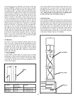
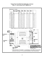
Page 20: ...19 Typical Two Side Wall Vent Application Always Refer To Vent Instructions 3308666 xxx...

Page 21: ...f this happens condensation could form on the frame and could promote rapid formation of frost If you suspect an improper seal apply a small bead of silicone all the way around the perimeter where the...

Page 22: ...conditions If so the cooling unit is good If the temperature of the water is above 43 degrees replace the cooling unit The outside temperature will affect the cooling capacity of the unit There is tha...

Page 23: ...22...

Page 24: ...communication between display and power modules The control system will revert to full automatic operation selecting the best energy source available with AC GAS priority The temperature setting will...

Page 25: ...arm is returned to the down position The absorption system will keep the compartment at the proper temperature for storage of ice Ice making is ac celerated if the thermostat is set to the coldest po...

Page 26: ...l type motor which is geared to the timing cam and ice ejector It is a one RPM motor To check the motor disconnect power to the appliance and test for continuity between the two leads If you DO NOT ha...

Page 27: ...toward the or side One full turn of the screw will make an 18 cc change in the amount of water DO NOT turn the screw more than one full turn at a time If the water level is too high it can also cause...

Page 28: ...27...

Page 29: ...28 ICE MAKER TYPICAL WIRING DIAGRAM...

Page 30: ...thermostat switches to its closed position after be ing sufficiently cooled by the ice in the mold The mold heater and motor are now energized The ejector blades begin to turn When the ejector blades...

Page 31: ...timing cam closes the holding switch providing a circuit to the motor that will assure completion of this revolution The mold heater remains energized The shut off arm will raise and lower again oper...

Page 32: ...rm thus operating its switch Near the completion of the second revolution the timing cam again closes the water valve switch This time a circuit is completed through the water valve solenoid its switc...

Page 33: ...32...

Reviews: