background image

25

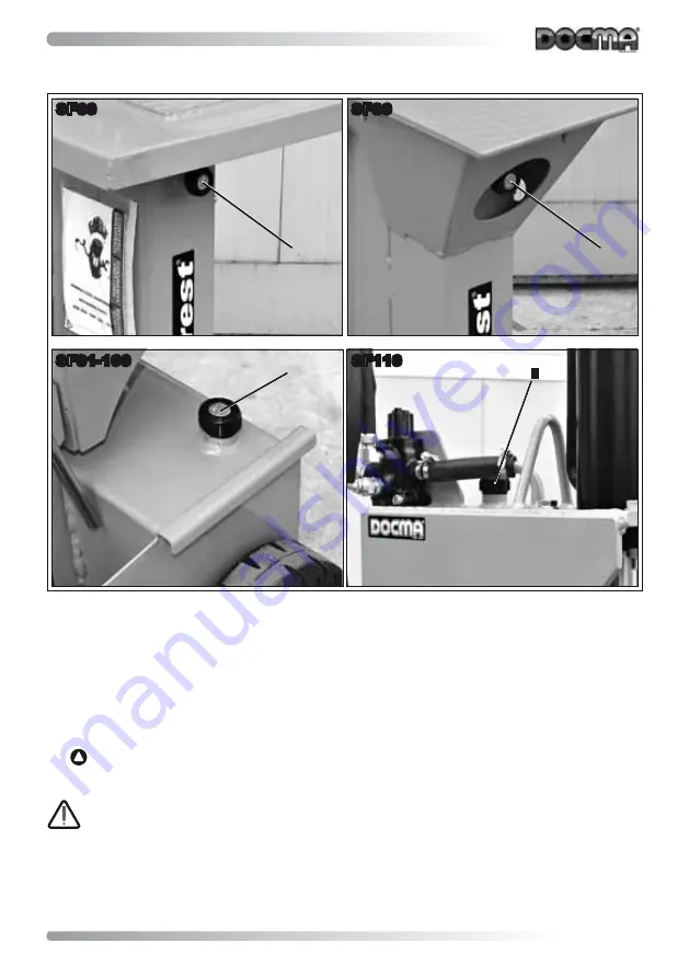
SF81-100

SF110

SF60

SF80

1

2

2

1

Fig. 12

Once a day check:


The tightness of the hydraulic couplings and hoses.

If the hydraulic hoses are damaged or visibly cracked they must be replaced.


The wear on the surfaces where the pads slide; if there is excessive play, have these checked or 

replaced by the reseller.


The edge of the blade on the wedge; if this needs to be sharpened, contact the reseller.


 Keep the motor cooling air inlet clean, using compressed air, and clean the motor casing and 

the power switch. 

When using compressed air, wear personal protective equipment (safety glasses, 

dust mask, etc.).

Summary of Contents for SF100

Page 1: ...User and maintenance manual models SF60 SF80 SF81 SF100 SF110 Log splitter ...

Page 2: ...ces 15 3 7 Stop functions 15 3 8 Safe working procedures 15 3 9 Residual risks 15 3 10 Safety signs 16 4 0 INSTALLATION 17 4 1 Transport 17 4 2 Positioning 17 4 3 Hitching to the tractor 18 4 4 Preliminary steps 18 4 5 Adjustments 19 4 5 1 Adjusting the travel of the wedge 19 4 5 2 Adjusting the workbench SF81 100 110 20 4 6 Test runs without logs 20 4 7 Choosing the log splitting wedge 21 4 8 Pre...

Page 3: ...litter can be supplied based on specific user requirements with electric motor dou ble pump for power cultivators for tractors with combustion engine with electric motor and tractor connection with hydraulic connection hoses Due to continuous technical evolution Docma Srl reserves the right to make changes to the machine at any time and without notice All rights reserved Total or partial reproduct...

Page 4: ...repla cements in order to be checked by the manufacturer The place of jurisdiction for any disputes is Verona The warranty does not cover any damage to the machine caused by transport and or movement improper or unskilled use of the machine by the user use with components that have been tampered with and or are faulty failure to perform properly the maintenance operations described in this manual ...

Page 5: ...achine the descriptions and operating procedures are nonetheless still valid 1 6 2 INTENDED USERS OF THIS MANUAL The manual is addressed to the user and the technicians authorised for the maintenance of the machine Users must not perform any operations reserved for the maintenance personnel or qualified technicians The manufacturer is not liable for any damage deriving from failure to observe this...

Page 6: ...e Fig 1 and describes all the important data as listed below Brand and manufacturer s identification Type and model of machine Serial number Power supply voltage V Thrust force t Cylinder travel mm Hydraulic oil content litres Overall mass kg Year of manufacture Fig 1 For the data referring to the machine do not use the information shown on this ra ting plate which is generic but rather the data p...

Page 7: ...ous reflections 2 4 VIBRATIONS If the machine is used in accordance with the instructions for correct operation the vibrations produced will not create situations of danger 2 5 NOISE EMISSIONS The machine is designed and built in such a way as to reduce the level of noise emissions at the source The level of noise during operation excluding models is very low 90 dB and consequently no precautions ...

Page 8: ...8 Fig 2 sf81 100 1 3 4 11 12 11 4 4 10 sf110 sf80 sf60 9 5 5 14 3 6 2 4 13 8 7 ...

Page 9: ...g 910001 SF60 220 HP 3 2 2 kW 220 6 92 910002 SF60 380 HP 3 2 2 kW 380 6 92 SF80 Cylinder travel Cutting height 540 mm 550 mm Code Version Technical data Tonnes t Mass kg 910003 SF80 220 HP 3 2 2kW 220 7 112 910004 SF80 380 HP 3 2 2 kW 380 7 112 910005 SF80 380 4 HP 4 3 kW 380 8 112 910006 SF80 RAPID 220 HP 3 2 2 kW 220 DP 8 112 910007 SF80 RAPID 380 HP 3 2 2 kW 380 DP 8 112 910008 SF80 RAPID 380 ...

Page 10: ... HP 6 cc 169 Subaru 7 120 910038 SF81 RAPID BENZ SUB BENZ HP 6 cc 169 DP Subaru 8 120 SF100 Cylinder travel Cutting height 540 mm 550 740 860 1030 mm Code Version Technical data Tonnes t Mass kg 920001 SF100 220 HP 3 2 2 kW 220 9 162 920002 SF100 380 HP 3 2 2 kW 380 9 162 920003 SF100 380 4 HP 4 3 kW 380 10 162 920004 SF100 RAPID 220 HP 3 2 2 kW 220 DP 10 162 920005 SF100 RAPID 380 HP 3 2 2 kW 380...

Page 11: ... 3P 11 216 930045 SF110 RAPID 380 PTO HP 3 2 2 kW 380 DP PTO 3P 11 216 930046 SF110 RAPID 380 4 PTO HP 4 3 kW 380 DP PTO 3P 11 216 930048 SF110 RAPID BENZ SUB BENZ HP 9 cc 270 DP Subaru 11 218 2 8 1 DIMENSIONS The overall dimensions are shown in the following table C B A Mod DIMENSIONS mm A B C SF60 1100 520 880 SF80 1100 620 650 680 900 1000 SF81 1100 520 550 650 900 1000 SF100 1400 620 650 680 9...

Page 12: ...n If in doubt contact the manufacturer s qualified personnel who will be happy to help Failure to observe the safety rules may cause accidents during the use and maintenance of the machine 3 1 GENERAL WARNINGS The manufacturer is not liable for any damage to people and or things due to failure to read or implement the instructions contained in this manual The user must observe the following warnin...

Page 13: ...manoeuvring take care not to cause accidents or damage to others and to the machine itself The drive shaft must only be connected and disconnected when the tractor engine is off Only use a drive shaft that is approved and suitable for the use of the log splitter this must be equipped with the complete original safety guards Do not stand in the area where the drive shaft is rotating during operatio...

Page 14: ...f the heart especially the ventricles making them quiver and causing arrhythmia this is a medical emergency that requires prompt hospital treatment Cardiopulmonary resuscitation is used as basic life sup port intervention however a defibrillator is essential for effective emergency treatment Burns at high current values the heat produced is greater than in the cases described above causing destruc...

Page 15: ...rs the following instructions must be follo wed While working the operator must keep his her hands on the special handles 5 Fig 2 During maintenance operations the machine must be disconnected from the power supply see 3 4 IMPROPER USE 3 9 RESIDUAL RISKS During the normal processing cycle and during maintenance the operator is exposed to a number of residual risks that due to the nature of the ope...

Page 16: ...l 2 Moving tools 3 Live equipment 4 Drive shaft rotation max 540 RPM REQUIREMENT white on blue background 5 Wear special personal protective equipment 6 Operating sequence for the log splitter control levers INDICATION in various colours 7 Additional information direction of rotation etc The warning labels with safety indications must not be removed covered or da maged if damaged they must immedia...

Page 17: ...ransport vehicle and make sure it is anchored securely so as to avoid problems during transport The same rules for loading the machine onto the transport vehicle must also be observed when unloading it The machine must be transported in the working configuration better still in the special packaging The machine must be handled manually The machine must be protected against all possible knocks and ...

Page 18: ...ine off Connect the tractor s power takeoff to the machine 4 Fig 6 using a suitable drive shaft fitted with guards The user must only use drive shafts with CE mark complete with declaration of con formity and instruction manual Read and carefully observe the instructions sup plied by the manufacturer of the drive shaft 4 4 PRELIMINARY STEPS Before starting the machine a series of checks are requir...

Page 19: ...dle on the machine downward using the left hand and then use the other hand to press the switch 1 Fig 3 wait around 2 seconds and then release the handle the machi ne will start without fluid hammer due to excess pressure 4 5 ADJUSTMENTS 4 5 1 ADJUSTING THE TRAVEL OF THE WEDGE If the length of the logs is less than the maximum travel of the wedge the working travel can be decre ased so as to reduc...

Page 20: ...s proceed as follows Remove the safety pin 1 Fig 8 Remove the pin 2 Fig 8 Hold the workbench securely with both hands 3 Fig 8 remove it and place it in the desired position Insert the pin 2 Fig 8 Insert the safety pin 1 Fig 8 1 3 2 SF81 100 110 SF81 100 110 Fig 8 4 6 TEST RUNS WITHOUT LOGS The machine is tested by the manufacturer before shipment however a number of checks are requi red Fig 9 1 Fi...

Page 21: ...ns more than once in order to become familiar with the controls and with the up down travel speed of the log splitting wedge 4 7 CHOOSING THE LOG SPLITTING WEDGE If the cross shaped wedge optional needs to be used simply fit it directly onto the existing standard wedge fitted on the machine s column positioning it so that the fastening pin matches the correspon ding centering slot on the standard ...

Page 22: ...sufficient general and technical knowledge to understand the contents of this manual and correctly interpret the figures drawings and diagrams knowledge of the main health and safety standards knowledge of how to behave in the event of emergencies where to find the personal protective equipment and how to use this correctly maintenance personnel as well as the characteristics described above must ...

Page 23: ...ust one hand is removed from a lever the wedge stops in the current position if both hands are removed from the levers the wedge returns to the fully open position It is absolutely prohibited to use other parts of the body feet knees etc to press the two control levers downwards When the log has been split release the levers the wedge will return to the fully open position ready for a new cycle If...

Page 24: ...Periodically depending on the intensity and frequency of operation lubricate the outside surface of the wedge support column with mineral oil SF110 If necessary abundantly grease the wedge guide groove so that this can slide smoothly preventing wear on the metal parts 6 5 MAINTENANCE OPERATIONS The operations described below must be performed at the specified intervals The manufacturer will accept...

Page 25: ...r on the surfaces where the pads slide if there is excessive play have these checked or replaced by the reseller The edge of the blade on the wedge if this needs to be sharpened contact the reseller Keep the motor cooling air inlet clean using compressed air and clean the motor casing and the power switch When using compressed air wear personal protective equipment safety glasses dust mask etc ...

Page 26: ... a suitably sized container see 2 8 TECHNICAL SPECIFICATIONS under the drain plug 1 Fig 13 Remove the drain plug 1 Fig 13 and let all the oil drain out To drain the oil faster remove the filler cap 1 or 2 Fig 12 The used oil must be stored in a sealed container and sent to a special centre for disposal according to the laws in force Add new AGIP SP 7735 7736 oil or equivalent until reaching the ri...

Page 27: ... voltage is not supplied b unsuitable adapter 1500 W and the right voltage is not supplied c voltage is insufficient due to mains problems d oil level insufficient for hydraulic circuit requirements Solution a use a shorter or higher cross section extension cord minimum wire size 2 5 mm2 for extensions longer than 15 m use wires larger than 2 5 mm2 b use 2000 2200 W adapters where possible avoid a...

Page 28: ... due to incorrect motor rotation direction b leaks between pump and gearbox are due to incorrect direction of rotation of the trac tor s power takeoff c leaks onto the ground from underneath the column may be due to bursting of the cylin der tubing due to broken or missing sliding pads d leaks onto the ground from underneath the column may be due to excessive lubrication of the galvanised column S...

Page 29: ...e components may be a source of danger while other materials lubricants paints hoses etc may pollute the environment When scrapping the machine the parts made from different materials rubber plastic etc must be separated for disposal in compliance with the legislation in force As regards the metal structure of the machine the parts made from steel and those made from other metals or alloys must be...

Page 30: ...30 10 0 WIRING DIAGRAMS 230 V WIRING DIAGRAM KEY 1 CASE K 900 2 STARTER MOTOR KB 04Uc 230 V 3 MOTOR PROTECTOR THERMAL OVERLOAD 4 ELECTRIC MOTOR ...

Page 31: ...31 400 V WIRING DIAGRAM KEY 1 CASE K 900 2 STARTER MOTOR KB 04 Uc 400 V 3 MOTOR PROTECTOR THERMAL OVERLOAD 4 ELECTRIC MOTOR ...

Page 32: ...32 11 0 HYDRAULIC DIAGRAMS KEY 1 ELECTRIC MOTOR 2 PUMP 3 DISTRIBUTOR 4 HYDRAULIC PISTON 5 OIL FILTER 6 OIL TANK HYDRAULIC SYSTEM DIAGRAM ...

Page 33: ...33 KEY 1 ELECTRIC MOTOR 2 DOUBLE PUMP 3 DISTRIBUTOR 4 HYDRAULIC PISTON 5 OIL FILTER 6 OIL TANK HYDRAULIC SYSTEM DIAGRAM WITH DOUBLE PUMP ...

Page 34: ...NOTES ...

Page 35: ...docma srl Via dell Artigianato 14 37057 San Giovanni Lupatoto Italia Tel 045 8732006 Fax 045 8739889 e mail info docma it www docma it ...

Reviews: