【
5-6
】
BODY
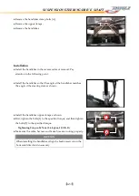
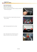
Front Fender Removal
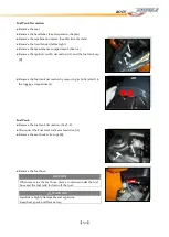
Maintenance Compartment
●
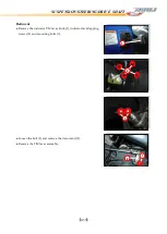
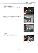
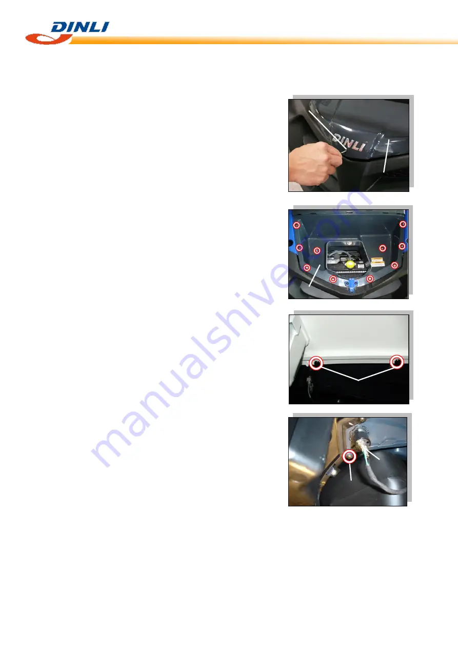
Remove the front rack. (See 5-3)
●
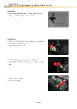
Remove front fender decoration [B] by inserting the opening stick
into the hole [A] to open it.
●
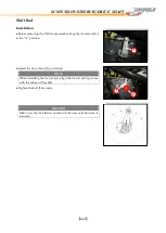
Remove the maintenance compartment [C] by removing its
screws and bolts.
●
[D] × 4 (left & right) (attach to the front fender).
●
[E] × 2 (left & right) (attach to the body decoration).
●
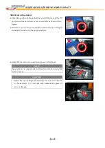
Remove the lead wire of the accessory socket [F].
A
B
D
E
C
E
F
Summary of Contents for DL-702 2008
Page 1: ...FOREWORD INDEX 0 0...
Page 41: ...3 11 BRAKE...
Page 180: ...6 70 ENGINE Install the starter motor...
Page 201: ...7 21 COOLING AND LUBRICATION SYSTEM Engine Lubrication System Chart...
Page 202: ...7 22 COOLING AND LUBRICATION SYSTEM Engine Lubrication System 1 2 3 1 2 3 1 2 3...
Page 203: ...7 23 COOLING AND LUBRICATION SYSTEM 1 2 3...
Page 235: ...7 32 ELECTRICAL SYSTEM Wiring Diagram...
Page 236: ...7 33 ELECTRICAL SYSTEM Wiring Diagram...
Page 237: ...7 34 7 34 ELECTRICAL SYSTEM ELECTRICAL SYSTEM...
Page 238: ...7 35 ELECTRICAL SYSTEM NOTE...
Page 240: ...9 2 PERIODIC MAINTENANCE...
Page 246: ...9 8 PERIODIC MAINTENANCE Intake Side...
Page 247: ...9 9 PERIODIC MAINTENANCE Exhaust Side Side...
Page 270: ...9 32 PERIODIC MAINTENANCE 1 2 3 4 18 19 12 16 17 21 13 14 15 22 23 5 6 7 8 9 12 10 11 20...

