ENGINE
【
6-29
】
W
45
○
●
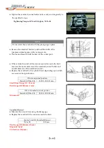
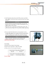
After
the
desired
seat
position
and
width
is
achieved,
use
the
45
○
cutter
slightly
to
clean
up
any
burrs
caused
by
the
previous
cutting
operation.
CAUTION
Do
not
use
lapping
compound
after
the
final
cut
is
made.
The
finished
valve
seat
should
have
a
velvety
smooth
finish
but
not
a
highly
polished
or
shiny
finish.
This
will
provide
a
soft
surface
for
the
final
seating
of
the
valve
which
will
occur
during
the
first
few
seconds
of
engine
operation.
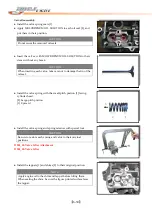
●
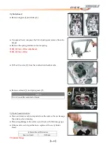
Clean
and
assemble
the
head
and
valve
components.
Use
the
vacuum
pump
gauge
to
cover
intake
and
exhaust
ports
and
check
for
leaks.
If
any
leaks
occur,
inspect
the
valve
seat
and
face
for
burrs
or
other
things
that
could
prevent
the
valve
from
sealing.
NOTE
D004
‐
Vacuum
Pump
Gauge
After
servicing
the
valve
seats,
be
sure
to
check
the
valve
clearance
after
the
cylinder
head
has
been
reinstalled.
Valve
Spring
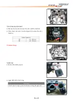
●
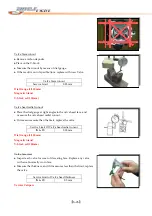
Measure
the
free
length
of
Valve
Spring.
●
Check
the
force
required
to
compress
the
spring.
●
If
the
result
is
not
correct,
replace
the
spring.
Service
Limit
of
Valve
spring
free
length
IN
&
EX
48.0
mm
Service
Limit
of
Valve
spring
free
length
IN
&
EX
19.0~21.4
kgf
/
36.50mm
Vernier
Calipers
Summary of Contents for DL-702 2008
Page 1: ...FOREWORD INDEX 0 0...
Page 41: ...3 11 BRAKE...
Page 180: ...6 70 ENGINE Install the starter motor...
Page 201: ...7 21 COOLING AND LUBRICATION SYSTEM Engine Lubrication System Chart...
Page 202: ...7 22 COOLING AND LUBRICATION SYSTEM Engine Lubrication System 1 2 3 1 2 3 1 2 3...
Page 203: ...7 23 COOLING AND LUBRICATION SYSTEM 1 2 3...
Page 235: ...7 32 ELECTRICAL SYSTEM Wiring Diagram...
Page 236: ...7 33 ELECTRICAL SYSTEM Wiring Diagram...
Page 237: ...7 34 7 34 ELECTRICAL SYSTEM ELECTRICAL SYSTEM...
Page 238: ...7 35 ELECTRICAL SYSTEM NOTE...
Page 240: ...9 2 PERIODIC MAINTENANCE...
Page 246: ...9 8 PERIODIC MAINTENANCE Intake Side...
Page 247: ...9 9 PERIODIC MAINTENANCE Exhaust Side Side...
Page 270: ...9 32 PERIODIC MAINTENANCE 1 2 3 4 18 19 12 16 17 21 13 14 15 22 23 5 6 7 8 9 12 10 11 20...

