13
©
Dinel, s.r.o. CLM–70
8 .
e
leCtriCal
ConneCtion
The level meter is connected to the follow-up (evaluation) device using a suitable cable with
an outer diameter of 6–8 mm by means of screw terminals located under the display module.
The recommended wire cross-section is 2× 0.5–0.75 mm2 (shielded) for the current version.
The positive pole (+U) is connected to the (+) terminal, the negative pole (0 V) to the (-) terminal,
and the shield (only for shielded cables) is connected to the ( ) terminal.
To connect a cable to the level meter:
1. Unscrew the upper lid nut.
2. Grasp the top edge of the display module and carefully slide it upwards carefully by slightly
swinging it.
3. If you are unable to grasp the display module, a small screwdriver can be used – insert it under
the edge and slightly lift the module from several sides.
4. Loosen the cable gland to pass a stripped power cable inside.
5.
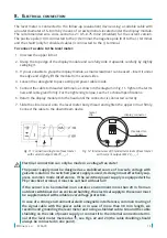
Connect the cable to threaded terminals, as shown in the diagram in Fig. 11. Tighten the termi-
nals and cable gland firmly. For the tightening torque, see the Technical Specifications.
6.
Return the display module into the head until the connector is connected correctly.
7.
Slide the silicone seal onto the level meter body thread and tighten the upper lid nut firmly.
Connect the cable to the downstream device.
display connector
threaded ter
-
minals
metal
clip
Fig. 12: Internal view of threaded terminals of level meter
with current output CLM-70_-_-_-I
Fig. 11: Connection diagram of level meter
with current output CLM-70_-_-_-I
Electrical connection can only be made in a voltage-free state!
The power supply must be designed as a stabilized source of low safe voltage with
galvanic isolation. If a switched power supply is used, its design must effectively sup
-
press common mode interference. If the switched power supply is equipped with a
PE protective terminal, it must be earthed without fail!
If the sensor is to be installed in an outdoor environment more than 20 m from an
outdoor switchboard or an enclosed building, the electrical supply to the sensor must
be supplemented with suitable overvoltage protection.
In case of a strong environmental electromagnetic interference, common routing of
the signal cable with the power cable or in case of more than 30 m in length, we
recommend grounding the level meter and using a shielded cable. Ground the cable
shielding on the side of power supply or connect it to the internal connection termi-
nal of the level meter marked as , see Figs. 22 and 23 (the cable shielding should
always be connected in one point).
Summary of Contents for CLM-70
Page 2: ......


