background image

25

© 

Dinel, s.r.o.      CLM–70


14 . 

f

ailUre


statUs


indiCation

The level meter is equipped with protection against fault voltage on the electrode, supply volt

-

age polarity reversal, short-term overvoltage, and current overload on the output.

Protection against direct contact is ensured:

• 

by safe voltage EN 61140

Electromagnetic compatibility is in accordance with the following standards:
• 

EN 55 011 (B), EN 61326-1, EN 61000-4-2 (A, 30kV)

• 

EN 61000-4-3 (A, 10V), EN 61000-4-4 (A, 2kV)

• 

EN 61000-4-5 (A, 2kV), EN 61000-4-6 (A, 10V)

Failure statuses are indicated using:

•  Display module (see chapter 9)

• 

Setting the failure current to the value selected in MENU – SERVICE – FAILURE MODE 

• 

Status messages in HART

®

 communication (applies to the current version with HART

®

 com

-

munication – 

I

)

15 . 

a

CCessories

16 . 

s

afety

proteCtion

Compatibility


and


explosion


proof

optional

 (for an extra fee)

• 

steel welding flange ON–G1, G1½

• 

stainless steel welding flange NN–G1, G1½

• 

fixing nut UM–G1, G1½ (stainless steel, plastic)

•  anchor roll KV–31 (for CLM–70–31 only)
• 

dust  proof  bushing  PR–31  (for  CLM–70–31 

only)

• 

extension cable for PK-70-1 display

standard 

(included in the price of the unit)

• 

1×  seal  (asbestos-free),  other  seals  by 

request (PTFE, Al, etc.)*

* Except type 61. For pressure resistance see 

the table in the accessories datasheet – seals

This equipment has been issued with a Declaration of Conformity pursuant to Act No. 90/2016 

Sb., as amended. The electrical equipment supplied complies with the requirements of appli

-

cable government regulations on safety and electromagnetic compatibility.

Summary of Contents for CLM-70

Page 1: ...level meter read the instructions in this manual and keep it carefully The manufacturer reserves the right to make alterations without a prior notice Capacitive level meter CLM 70 INSTRUCTION MANUAL Applies to firmware version 1 0 ...

Page 2: ......

Page 3: ...0 1 Basic settings 15 10 2 Service settings 18 10 3 Additional functions 19 11 HART protocol 21 12 How to install a custom measuring electrode replace or shorten the electrode 22 13 Order code 24 14 Failure status indication 24 15 Accessories 25 16 Safety protection compatibility and explosion proof 25 17 Use manipulation and maintenance 25 18 Marking of labels 26 19 Menu structure 27 20 Technical...

Page 4: ...ce tube or a pair of parallel electrodes for measuring liquids in non conductive tanks All operations described in this instruction manual have to be carried out by trained personnelorbyanaccreditedpersononly Warrantyandpostwarrantyservicemust be exclusively carried out by the manufacturer Improper use installation or set up of the sensor can lead to crashes in the ap plication The manufacturer is...

Page 5: ...on the electrode may occur Length 0 5 8 m CLM 70_ 20 Uncoated stainless steel rod electrode with reference tube for level measurement of unpolluted and electrically non conductive liquids oil diesel fuel petrol Length 0 2 3 m CLM 70_ 22 Coated stainless steel rod electrode FEP with reference tube for level measurement of clean electrically conductive liquids e g in plastic and glass tanks and for ...

Page 6: ...70 4 M16x1 5 27 46 electrode holder electrode thread coated electrode CLM 70_ 61 Variant CLM 70 with a cable gland for protective hose High temperature performance CLM 70_T Process connection Tri clamp types of thread G1 except type 61 1 NPT except type 61 Except type CLM 70_ 61 Only for type CLM 70_ 11 12 13 32 ...

Page 7: ...nce pipe CLM 70_ 30 CLM 70_ 31 CLM 70_ 32 compression spring hopper wall KV 31 PR 31 anchor with ball joint rope electrode coated rope electrode coated weight rope electrode weight anchor roll KV 31 or dust proof bushing PR 31 see accessories ...

Page 8: ...re bracket lid etc and then connected to a permanently submerged metal object or steel reinforcements in concrete armouring E electrode length mm select so that the electrode end is submerged at least 20 mm below the lowest measured level h distance from the bottom at least 50 mm a distance from the wall at least approx E 20 d diameter of the auxiliary tubular vessel at least 40 E 20 smaller dimen...

Page 9: ...EEP METAL AND CONCRETE SILOS APPLIES TO CLM 70_ 30 32 To be connected to the armouring Concrete silo Metal tank E electrode length mm to be selected so that the electrode end is placed at least 20 mm below the lowest measured level h distance from the bottom at least 100 mm a distance from the wall at least E 20 otherwise choose as large as possible as far from the wall as possible in the middle b...

Page 10: ...g to the hopper casing Fig 4 Installation of the level meter with a rope electrode and anchor E electrode length mm submerge the electrode end at least 20 mm below the lowest measured level h distance from the bottom at least 30 mm a distance from the wall at least E 20 Fig 5 Installation of the level meter with a reference electrode ROPE ELECTRODE WITH AN ANCHOR APPLIES TO CLM 70_ 31 AGGRESSIVE L...

Page 11: ...used to thermally insulate the electronics part of the meter from the high operating temperature The ex tension must not be embedded in the insulation more than 50 mm Fig 7 A shielding cover protecting against direct sunlight Fig 6 Installation of the level meter in an insulated tank COVERING THE LEVEL METER APPLIES TO All types TANK WITH INSULATION APPLIES TO CLM 70NT _ The level meter is not rec...

Page 12: ...0 type the manufacturer is not responsible for defects related to the connected measuring electrode It is intended for non conductive media only as only a non insulated rod or rope can be connected VARIANT WITHOUT AN ELECTRODE APPLIES TO CLM 70_ 00 It is advisable to run the cable un der a cable gland sagging down wards This prevents possible ingress of moisture through the cable gland Rain and co...

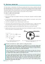
Page 13: ... onto the level meter body thread and tighten the upper lid nut firmly Connect the cable to the downstream device display connector threaded ter minals metal clip Fig 12 Internal view of threaded terminals of level meter with current output CLM 70_ _ _ I Fig 11 Connection diagram of level meter with current output CLM 70_ _ _ I Electrical connection can only be made in a voltage free state The pow...

Page 14: ...e configured via HART When the set up is complete the display module can be disconnected and the level meter takes measurements without it Status indication lower left corner of the display symbol lights permanently the level meter is locked against unauthorized settings a password is required for unlocking see MENU PASSWORD Warning signs FIXED OUTPUT the output current is fixed to a constant valu...

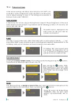
Page 15: ...n which the level meter should meas ure must be set The output current range the OUTPUT line of 4 mA 20 mA output is then assigned to this range And the value shown on the meter display DISPLAY line In the upper right corner below the sign ACTUAL CAPACITY the value of the currently meas ured level is displayed ACTUAL CAPACITY current meas ured capacity CAPACITY definition of the min max capacity D...

Page 16: ...evel Meter ULM 70 ESC OK 1745 mm and ESC OK www dinel cz Ultrasonic Level Meter ULM 70 ESC OK 1745 mm buttons to set damping 3 After finishing the settings press the ESC OK www dinel cz Ultrasonic Level Meter ULM 70 ESC OK 1745 mm button to save the data Press the ESC OK www dinel cz Ultrasonic Level Meter ULM 70 ESC OK 1745 mm button suc cessively to exit the menu the level meter returns to the m...

Page 17: ... a known level H1 e g 15 In the SERVICE CAPACITY menu item the capacity at this known flooding 15 can be found This capacity is noted down and denoted as C1 e g 35 pF 2 Flood the tank to another known level H2 e g 78 In the SERVICE CAPACITY menu item the capacity at this known flooding 78 can be found This capacity is noted down and denoted as C2 e g 126 pF 3 The capacities at the limit points of ...

Page 18: ...short time After loading the default values the display shows DONE and the message Press Esc to exit FACTORY DEFAULT ARE YOU SURE RUNNING DONE PRESS ESC TO EXIT FAILURE MODE HART FACTORY DEFAULT RESET FACTORY DEFAULT FACTORY DEFAULT FAILURE MODE HART FACTORY DEFAULT RESET RESET ARE YOU SURE During the restart the display shows RUNNING Then the level meter switches off automatically and re starts F...

Page 19: ...mode transfers all data except the TEACHING mode settings and the HART protocol configuration 10 3 Additional functions Additional functions include modes for copying settings or detecting the actual loop cur rent Further they include password based locking of modification and the level meter dis play module version information All these functions are accessible from the main menu DIAGNOSTIC CAPAC...

Page 20: ... data is saved using the button PASSWORD Here the level meter can be locked to prevent unauthorised data editing Once the password is activated the data can be read but cannot be edited When attempting to edit the NO PASSWORD message appears on display The password can have any five digit combination The combination of 00000 is reserved for the password deactivation Displaying the status after con...

Page 21: ...nd 49 Fig 13 Connection of peripheral devices with the HART protocol RS232 USB HART communicator 250 R Voltage source CLM 70_ _ _ _ I 11 HART protocol A universal communication interface for the communication of peripheral devices with the level meter Data communication runs in the same line as the analogue signal 4 20 mA with out disturbing its function To set the level meter and collect measured...

Page 22: ...mended by the glue manufac turer after then the level meter is ready for installation 5 Perform the setting of the level meter How to replace the measuring electrode applies only to variants 10 30 and 31 1 Heat the place of the threaded joint of the electrode and the electrode holder see Figs 15 and 17 using a heat gun to a temperature of approx 120 150 C or 220 250 C for the high temperature vari...

Page 23: ...60 mm For the rope shortening cutting pliers are the best option Be careful not to fray the end of the rope 3 Slide the rope back into the weight and secure it by tightening all three screws 4 If the electrode has been removed from the electrode holder reas semble them see points from 3 to 7 of How to replace the meas uring electrode For places to be heated see How to replace the measuring electro...

Page 24: ...th 0 2 3 m 30 uncoated rope electrode length 1 20 m Cl50 process connection cannot be selected 31 uncoated rope electrode with anchor length 1 20 m Cl50 process connection cannot be selected 32 electrode with insulated cable FEP and insulated weight PTFE length 1 12 m NPT process connection cannot be selected 61 two fully coated stainless steel rod electrodes FEP insulation length 0 2 2 m not appl...

Page 25: ...sages in HART communication applies to the current version with HART com munication I 15 Accessories 16 Safety protection compatibility and explosion proof optional for an extra fee steel welding flange ON G1 G1 stainless steel welding flange NN G1 G1 fixingnutUM G1 G1 stainlesssteel plastic anchor roll KV 31 for CLM 70 31 only dust proof bushing PR 31 for CLM 70 31 only extension cable for PK 70 ...

Page 26: ... CLM 70_ _ _ _ I _ _ type Temperature range as per type 02 ta 30 70 C 06 ta 30 70 C 10 ta 30 60 C 20 ta 30 60 C The level meter requires no operator to work During operation the operator of the techno logical unit is informed of the measured substance level via a related display device and via the level meter display at the installation site Maintenance of the device consists in checking the integ...

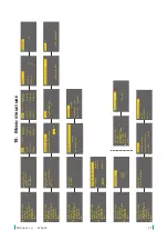
Page 27: ...SETTINGS PASSWORD LANGUAGE INFO BASIC SETTINGS SERVICE DIAGNOSTIC CLONE SETTINGS PASSWORD LANGUAGE INFO MIN CAPACITY MAX CAPACITY UNITS DAMPING ACTUAL CAPACITY 023 56 pF ACTUAL CAPACITY 023 56 pF OUTPUT 04 00 mA CAPACITY 06000 pF DISPLAY 00000 OUTPUT 20 00 mA CAPACITY 00250 pF DISPLAY 00100 UNITS CAPACITY pF DISPLAY DAMPING FAILURE MODE HART FACTORY DEFAULT RESET FAILURE MODE 4 00 MEASUREMENT ERRO...

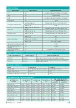
Page 28: ...to 70 C 1 pF do 100 pF 1 of the measured value from 100 to 3 000 pF Measuring frequency 100 to 800 kHz Non linearity electronics max 1 Damping time constant Adjustable 0 99 s Maximum slew rate 1s 0 100 for damping 0 s Current output error max 80 uA Display settings display module Protection class IP67 Maximum length of measuring electrodes see dimensional drawing Ambient temperature range 30 C to ...

Page 29: ... 70_ 61 G1 G1 for type 61 G1 Tapered pipe thread NPT 1 NPT Seamless connection Tri Clamp ø 50 5 mm Cl50 Device classification according to ČSN EN 60079 10 1 and ČSN EN 60079 10 2 sensor performance electrode type device classification CLM 70N all types Basic performance for use in non explosive areas CLM 70NT all types High temperature performance for use in non explosive areas max 200 C Temperatu...

Page 30: ... 31 s PR 40 C 130 C 40 C 130 C 30 C 70 C CLM 70NT 32 40 C 130 C 40 C 130 C 30 C 70 C CLM 70NT 61 tp temperature in process connection place tm medium temperature on the electrode ta ambient temperature at the head with electronics Fig 19 Illustration of temperature measurement areas Pressure resistance high temperature performance performance variant maximum overpressure for temperature tp up to 3...

Page 31: ...g material and protected against shocks and weather conditions Store the device in the original packing material in dry areas covered from the weather conditions with moisture up to 85 without any effects of chemically active substances Storage temperature range is from 10 C to 50 C Error codes ERROR NUMBER CAUSE REMEDY ERROR 1 Measuring module failure or short circuit on the electrode Remove the ...

Page 32: ...Dinel s r o U Tescomy 249 760 01 Zlín Czech Republic phone 420 577 002 002 e mail sale dinel cz www dinel cz Find the updated version at www dinel cz version 08 2017 industrial electronics 04 2020 ...

Reviews: