


Product Information
Safety technics modular generation in metal housing version 08 dated: 2009-04-10 page 6 from 32
Features:
Dual channel motion and standstill monitoring.
Connection for an encoderto the RJ45 jack or 2 PNP-proximity sensors to IN1 and IN2
Status indicators.
Programmable speed setting
The DNDS complies with the safety requirements( see below)
The circuit is redundant with built-in self-monitoring.
The safety function remains effective in the case of a component failure.
Motion detection of machines
The motion detection of an actuation can be accomplished via an encoder, resolver or 2 PNP-proximity sensors. The encoder or
Resolver is connected via a cable adapter DNDA 15/8 or 25/8 to the DNDS.
For motion detection via 2 PNP proximity sensors the inputs IN1 and IN2 are used. When mounting the proximity sensors on a
tooth wheel, attention must be paid to mount them in a way, so always at least one of the two sensors is activated.
Function of the inputs
IN- inputs
:
IN1 and IN2 are used, if proximity sensors are used for speed monitoring. Two PNP switches are necessary.
By connecting IN2 constantly to 24V DC and IN1 left open, the monitoring module is forced into detecting solid standstill. In this
way the monitoring module is disabled from monitoring.
Inputs for function modes
Monitoring modules:
DNDS 1EG V9 and
DNDS 1RG V1
D- inputs
: 00–15, for setting of the automatic operation mode
(mode1).
D-inputs are only of importance if at least one F-input is connected to
24V.
F-inputs
: 01-15 for reduction of setting D-inputs setting from 100 to
25%. The F-inputs are a switch over between tool setting mode (mode
2) respectively semi-automatic mode (mode 3), “F are NC” and mode1.
At least one F- is connected to 24V.
R1-input
: for setting the mode 3
R1-input is only active, if F1-F4 are off.
SH-input:
for setting the mode 2
SH-input is only active, if R1 and F-inputs are NC.
Monitoring modules: DNDS 1EG V7A, DNDS 1EGV7C and
DNDS 1RG V2, DNDS 1RG V3C
M-
rather
MT-inputs:
These inputs can be used, if the automatic
mode (mode 1) has not to be monitored. Only D- or M- rather MT-
inputs can be used. The M- rather MT-inputs are a switch over be-
tween tool setting mode (mode 2) respectively semi-automatic mode
(mode3), “M, MT are NC” and mode1. M-, MT-inputs connected to
24V.
D- inputs
: D1-D6 = 0-63, for setting of mode 1. The D-inputs are a
switch over between mode 2 respectively mode 3 “D = are NC” and
mode 1. Any D-input connected to 24V.
R1-input
: for setting the mode 3
R1-input is only active, if D-, M- respectively MT-inputs are NC.
SH-input:
for setting the mode 2. SH-input is only active, if R1, D-, M-
respectively MT-inputs are NC.
DNDS 1EG V9 and DNDS 1RG V1: Setting the function modes via the inputs
SH-input
R1-input
F-inputs
D1 to D4 inputs
Function modes
Dx at 24V
Standstill
24V
Dx at 24V
Mode 2
24V
Dx at 24V
Mode 3
Fx at 24V
Dx at 24V
Automatic
Priority: F-inputs > R1-input > SH-input
DNDS 1EG V7A and DNDS 1RG V2
:
Setting the function modes via the inputs
SH-input
R1-input
D1 to D6 inputs
M11 & M12 rather MT-inputs
Function modes
Standstill
24V
Mode 2
24V
Mode 3
Dx at 24V
Automatic
M11 & M12 rather MT at 24V
No monitoring
Priority: M-inputs, rather MT > D-inputs > F-inputs > R1-input > SH-input
Mode 1: Automatic mode
Mode 2: tool setting mode
Mode 3: semi automatic mode
The inputs F1-F4, D1-D6 M11, M12, R1 and SH are delayed 1s on switch off.
10ms switch on decelerated
1,0 switch off decelerated
inputs: D, F, R1 & SH
function
10ms
1s
24V
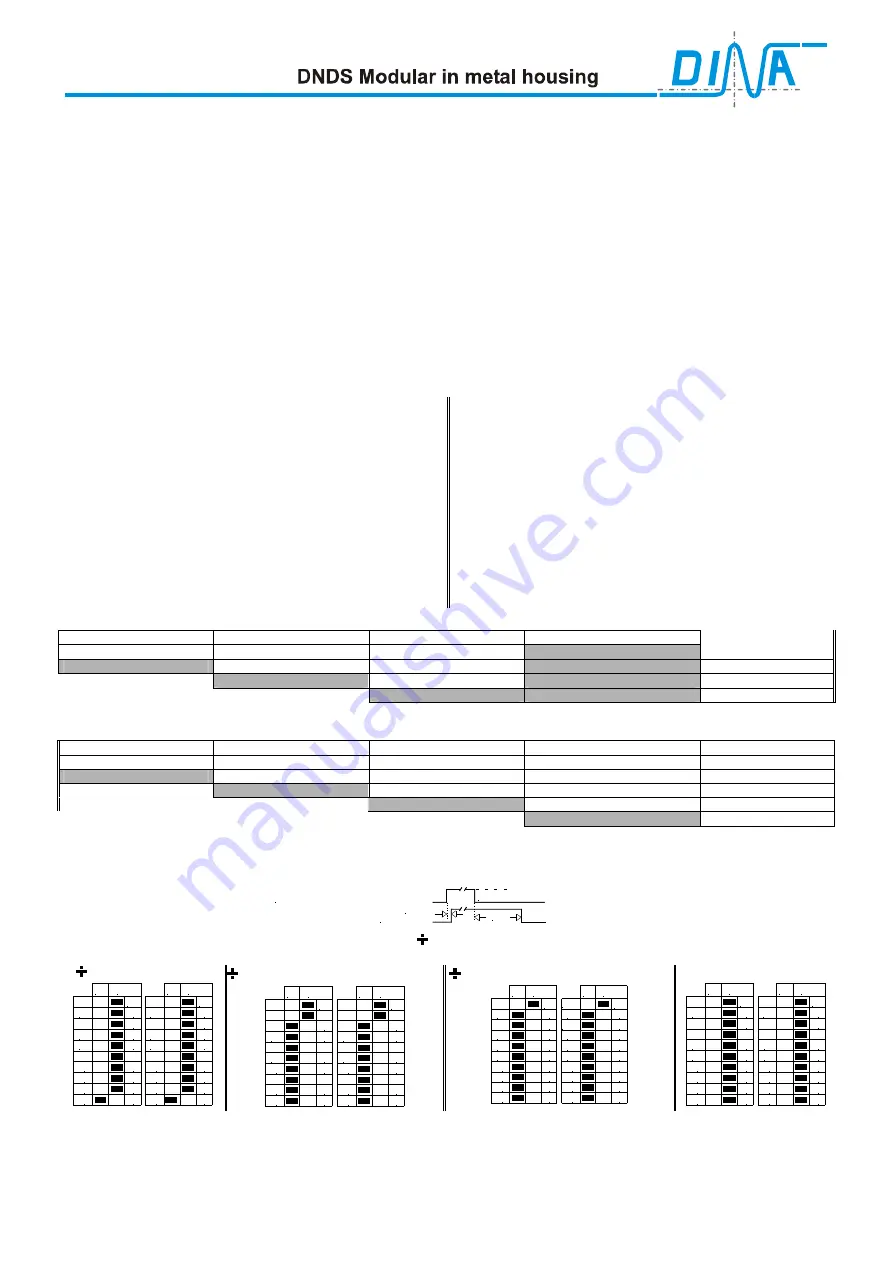
Setting of division factor:
Setting of division factor ( ) for the adaptation of the encoder frequency for the moni-
toring module. The DIP-switches are located at the monitoring module.
= minimal
= 2(1+1) = 4
1
2
3
4
5
6
7
8
9
10
S1
on
1
2
4
8
16
32
64
128
x2
1
2
3
4
5
6
7
8
9
10
S2
on
1
2
4
8
16
32
64
128
x2
Filter
Filter
=
2(1+1+2+4+8+16+32+64+128)=512
1
2
3
4
5
6
7
8
9
10
S1
on
1
2
4
8
16
32
64
128
x2
1
2
3
4
5
6
7
8
9
10
S2
on
1
2
4
8
16
32
64
128
x2
Filter
Filter
=
4(1+1+2+4+8+16+32+ 64+128)=1024
1
2
3
4
5
6
7
8
9
10
S1
on
1
2
4
8
16
32
64
128
x4
1
2
3
4
5
6
7
8
9
10
S2
on
1
2
4
8
16
32
64
128
x4
Filter
Filter
illegal
1
2
3
4
5
6
7
8
9
10
S1
on
1
2
4
8
16
32
64
128
x2
1
2
3
4
5
6
7
8
9
10
S2
on
1
2
4
8
16
32
64
128
x2
Filter
Filter
Function of the switch position 9 at S1 and S2
:
Position 9 off: adjusted divisor via position 1 to 8 will be multiplied by 2.
Position 9 ON: adjusted divisor via position 1 to 8 will be multiplied by 4.
Function of the switch position 10 at S1 and S2
:
Position 10 off: Suppression of the Encoder Frequency less than 50Hz. Suppression of single channel encoder Frequency less than 800Hz
Position 10 ON: Suppression of the Encoder Frequency less than 25Hz. Suppression of single channel encoder Frequency less than 400Hz


