


Product Information
Safety technics modular generation in metal housing version 08 dated: 2009-04-10 page 13 from 32
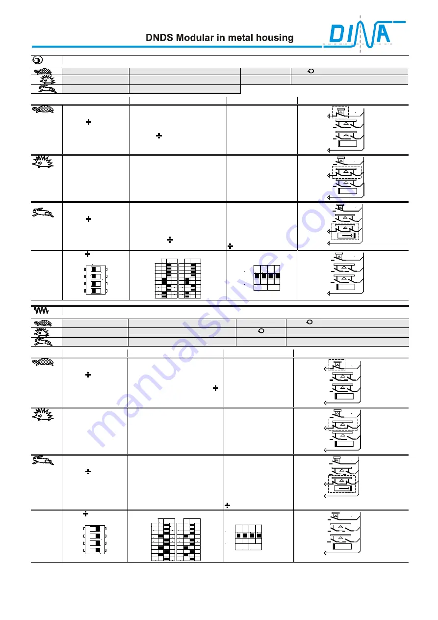
DNDS 1EG V9: monitoring spindle
800min
-1
Tool setting speed (mode2)
Encoder pulses
256I /
5000min
-1
Mode3
n
max
+ 10%
Switch off at
(+10% = Safety distance)
n
max
=18000min
-1
Automatic operating mode (mode1)
Mode
Calculation
Note
Extern Contacts,
Contacts
Mode2
Step 1
Calculation of the
divisor ( ) and the
monitoring frequency
for mode2
Ratio mode 3 to mode 2 =
5500min
-1
/880min
-1
=6,25
256I x 880 min
-1
/ 60s = 3755Hz
3755 Hz /
96Hz
= 39,11
≈
≈
≈
≈
2(19+
1
)
2(19+
1
)
=
BA2, mode2
Adjustment S3
R1 and SH table
positions 0 is possible =
96Hz
.
96Hz
=
mode2-frequency
SH
D3, D4
24V
Tip switch
Permission key
Protection
cover
Mode3
Step 2
Calculation of the
monitoring frequency
for mode3
6,25 x 96Hz =
600Hz
Adjustment S3
R1 and SH table
positions 0 is possible =
600Hz
600Hz
=
mode3-frequency
R1
D3, D4
24V
Tip switch
Permission
key
Protection
cover
Mode1
Step 3
Calculation of the
divisor ( ) and the
monitoring frequency
for mode1
19800min
-1
x 256I/ 60s = 84480Hz
84480Hz / 2(19+1) = 2112Hz
Max. Frequency in D-Table =1250Hz
84480Hz
/ 2(19+1+32) =
812Hz
812Hz = 90% of 900Hz
2(19+1+32) =
n
max
D-Table, position 12 =
D3 and D4 = 900Hz
F-Table, position 14 =
F2, F3 and F4 = 90%
90% of 900Hz =
812Hz
812Hz
=mode1-frequency
variable
F2, F3, F4
D3, D4
24V
Tip switch
Permission key
Protection
cover
DIP
switches
Adjustment
Table1,
variable
o
n
1
2
3
4
S3
2x(19+32+1)=2(1+2+16+32+1)=104
1
2
3
4
5
6
7
8
9
10
S1
on
1
2
4
8
16
32
64
128
x2
S2
on
Filter
Filter
1
2
3
4
5
6
7
8
9
10
1
2
4
8
16
32
64
128
x2
on
1
2
3
4
S4
5V 0V WES
Standstill
D3, D4
24V
Tip switch
Permission key
Protection
cover
DNDS 1EG V9: monitoring axis
v
= 2m x min
-1
Tool setting speed (mode2)
Encoder pulses
2048I /
v
= 5m x min
-1
Mode3
10mm /
Ascending gradient
v
max
=18m x min
-1
Automatic operating mode (mode1)
v
+ 10%
Switch off at
(+10% = Safety distance)
Mode
Calculation
Note
Extern
Contacts
Contacts
Mode2
Step 1
Calculation of the
divisor ( ) and the
monitoring frequency
for mode2
Ratio mode 3 to mode 2 =
5,5m / 2,2m = 2,5
2,2m x min
-1
/ 10mm = 220min
-1
220min
-1
x 2048I / 60s = 7509Hz
7509Hz /
50Hz
=150=2(74+
1
) =
(
)
Adjustment S3
R1 and SH table
positions 0 is possible =
50Hz
.
50Hz
=
mode2-frequency
SH
D2, D3
24V
Tip switch
Permission key
Protection cover
Mode3
Step 2
Calculation of the
monitoring frequency
for mode3
2,5 x 50Hz =
125Hz
=
Adjustment S3
R1 and SH table
positions 0 is possible =
125Hz
125Hz
=
mode3-frequency
R1
D2, D3
24V
Tip switch
Permission key
Protection cover
Mode1
Step 3
Calculation of the
divisor ( ) and the
monitoring frequency
for mode1
19,8m x min
-1
/ 10mm = 1980min
-1
1980min
-1
x 2048I / 60s = 67584Hz
67584Hz / 2(74+1) =
450Hz
D-Table, position 06 =
D2 and D3 = 450Hz
F-Table, position 15 =
F1-F4 = 100%
100% of 450Hz =
450Hz
450Hz
=
mode1-frequency
constant
F1-F4
D2, D3
24V
Tip switch
Permission key
Protection
cover
DIP
switches
Adjustment
Table1
constant
o
n
1
2
3
4
S3
2(74+1) = 2(2+8+64+1) = 150
1
2
3
4
5
6
7
8
9
10
S1
on
1
2
4
8
16
32
64
128
x2
S2
on
Filter
Filter
1
2
3
4
5
6
7
8
9
10
1
2
4
8
16
32
64
128
x2
on
1
2
3
4
S4
5V 0V WES
Standstill
D2, D3
24V
Tip switch
Permission key
Protection cover
The switch off limits of the speed monitoring have to be tested.
The safety relevant connection, as example to the SH-, R1-input and to the F-inputs, have to be mounted in a cable
channel. The total concept of the specified category must be validated involving the whole control unit.


