


Product Information
Safety technics modular generation in metal housing version 08 dated: 2009-04-10 page 14 from 32
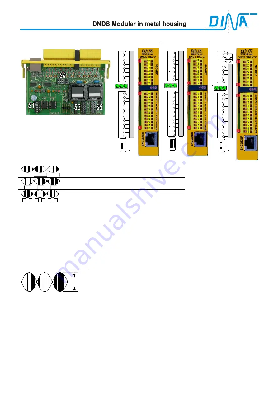
DNDS 1RG V1, DNDS 1RG V2 and DNDS 1RG V3C
DNDS 1RG V1
DNDS 1RG V2
DNDS 1RG V3C
Function of the DIP switches
UB
STOP
IN2
IN1
D1
D2
D3
D4
SH
R1
F1
F2
F3
F4
E
n
c
o
d
e
r
SPEED
UB
STOP
IN2
IN1
D1
D2
D3
D4
SH
R1
D5
D6
M11
M12
E
n
c
o
d
er
SPEED
UB
STOP
IN2
IN1
D1
D2
D3
D4
SH
R1
D5
D6
MT
O1
O2
24V
E
n
c
o
d
e
r
SPEED
S1 Function:
Position 3 & 6 on: N
o frequency multiplication
Position 2 & 5 on
: Frequency doubling (x2)
Position 1 & 4 on
: Frequency quadruplicating (x4)
S3, S5 function
:
Selection of monitoring frequencies for tool setting mode (mode 2) and semi automatic mode (mode3).
See adjusting table, R1 and SH Table.
S4 function:
Positions 1 & 2 on:
Speed output automatic restart disable.
If there is an overspeed, the output contacts SPEED at the output module switch-off and remain switched off also
during standstill. The contacts close again, if the power supply will be turned off
≥
≥
≥
≥
2s
.
Positions 1 & 2 off:
Speed output automatic restart enable. If there is an overspeed, the output contacts SPEED
at the output module switch-off. The contacts close again, if the actual speed is 10% less than the adjusted speed.
S4 Function position 3 to 6
: Adjusting of the amplification for the input voltage at the RJ45 connector as follows:
U
In
Position 3 to 6 off: U
In
≈
≈
≈
≈
7Vss
Position 3 and 5 on: U
In
≈
≈
≈
≈
5Vss
Position 4 and 6 on: U
In
≈
≈
≈
≈
3,2Vss
Position 3 and 6 on: U
In
≈
≈
≈
≈
2Vss
Product description
The monitoring modules
DNDS 1RG V1, V2 and V3C
are used, if the movement control of a drive is made by a
resolver. The resolver can may be connected via the cable adapter DNDA. Different cable adapters are available to
meet the individual connector and pin configurations. See product information DNDA.
The connection of the monitoring module to the resolver is high impedance, in order not to affect the resolver
signals.
The modulated signals (sine & cosine) are demodulated and amplified on the monitoring module. After the
demodulation the frequency is supplied by two channels to the monitoring electronic.
The resolver signals are constantly monitored. If one pair of resolver signals fails as example (+ Sine / -Sine) the
module switches the outputs off .
If the module is monitored standstill and a motion is detected, the module will switch off the outputs at the output
modules. The outputs will stay off even if there is no more motion. To reset, the SH signal may be applied shortly or
the unit may be power cycled.
The frequency values in the follow table = Encoder frequency multiplied with 1, 2 or 4


