background image

Page 23 of 35 


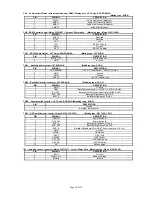
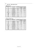
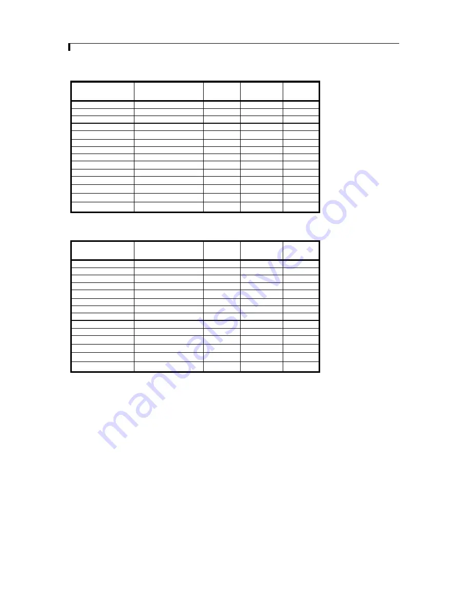
Appendix I – Mode Support Table


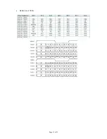
HDMI (P3) port : 

Mode Resolution 

Clk 

[MHz] Horizontal 

freq [KHz] 

Vertical 

freq [Hz]

T_70 720x400 

70Hz 

28.322 

31.469 

70.087 

V_60 640x480 

60Hz 

25.175 

31.469 

59.940 

SV_60 800x600 

60Hz 

40.000 

37.879 

60.317 

X_60 1024x768 

60Hz 

65.000 

48.363 

60.004 

SX_60 1280x1024 

60Hz 

108 

63.81 

60.020 

UX_60 

1600x1200 60Hz  

162 

75.000 

60 

WUX_60 1920x1080 

60Hz 

172.8 

67.5 60 

WUX_60 1920x1200 

60Hz 

193.2 

74.5 60 

1080p60 1920x1080p 

60Hz 

135 67.5 60 

1080i60 1920x1080i 

60Hz 

74.14 

33.7 60 

1080i50 1920x1080i 

50Hz 

74.184 

28.1 50 

720p60 

1280x720P


60Hz 

74.25 45  60 

576p50 

720x576P


50Hz 

26.9568 31.2 

50 

480p60 

720x480P


 60Hz 

26.9568 31.4 

60 


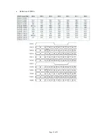
Display Port (P4) port :    

Mode Resolution 

Clk 

[MHz] Horizontal 

freq [KHz] 

Vertical 

freq [Hz]

T_70 720x400 

70Hz 

28.322 

31.469 

70.087 

V_60 640x480 

60Hz 

25.175 

31.469 

59.940 

SV_60 800x600 

60Hz 

40.000 

37.879 

60.317 

X_60 1024x768 

60Hz 

65.000 

48.363 

60.004 

SX_60 1280x1024 

60Hz 

108 

63.81 

60.020 

UX_60 

1600x1200 60Hz  

162 

75.000 

60 

WUX_60 1920x1080 

60Hz 

172.8 

67.5 60 

WUX_60 1920x1200 

60Hz 

193.2 

74.5 60 

1080p60 1920x1080p 

60Hz 

135 67.5 60 

1080i60 1920x1080i 

60Hz 

74.14 

33.7 60 

1080i50 1920x1080i 

50Hz 

74.184 

28.1 50 

720p60 

1280x720P


60Hz 

74.25 45  60 

576p50 

720x576P


50Hz 

26.9568 31.2 

50 

480p60 

720x480P


 60Hz 

26.9568 31.4 

60 
Summary of Contents for ALR-1920-120

Page 1: ...nectors pinouts jumpers Essential connection information 18 Controller dimensions 19 Application notes 20 Troubleshooting 21 Specifications 23 Appendix I Mode Support Table 24 Appendix II RS 232 control protocols 28 Appendix III DDC CI support at HDMI Display port 29 Appendix IV Mapping definition 33 Appendix V DV remote control unit work for ALR 1920 120 34 Warranty Caution Limitation of Liabilit...

Page 2: ...ment for each panel Connector reference in following section Assembly notes Check controller switch jumper settings errors may damage the panel Prepare the signal source Connect the parts Understand the operation and functions in following section IMPORTANT USAGE NOTE This product is for use by system developers and integrators the manufacturer accepts no liability for damage or injury caused by t...

Page 3: ...verter cable 6 OSD switch mount control 7 OSD controls cable 8 Optional Controller status LED1 9 Optional IR sensor 10 RS 232 control interface 11 HDMI input 12 Display Port Input 13 Audio output Stereo with amplication from HDMI Display Port 14 SPDIF Audio output 15 Panel backlight control for 120Hz panel used only 16 Power input 12VDC 24VDC Digital View offers a range of accessories such as list...

Page 4: ...l type 7 OSD switch mount controls cable The cables to the function switches should be of suitable quality and length so that impedance does not affect performance Generally lengths up to 1 metre 3 feet should be acceptable 8 Controller status LED Optional This LED indicates the controller status The pin direction of the LED should be corrected for right colour indication Red colour stands for sta...

Page 5: ...g It is recommended that a clearance of at least 10mm is provided above and 5mm below the controller when mounted Additionally consideration should be given to Electrical insulation Grounding EMI shielding Cable management Note It is important to keep panel signal cables apart from the inverter backlight cables to prevent signal interference Heat Ventilation Heat generated from other sources for e...

Page 6: ...cable to the connector P3 on the controller board 12 Display port cable Plug the Display port cable to connector P4 on the controller board 13 Audio output connector SPDIF audio connector audio output port CN1 support audio output stereo from the HDMI Display Port and CN11 support audio SPDIF audio output from HDMI Display Port audio source inputted It requires to select the audio port Speakers SP...

Page 7: ...r appear on RIGHT hand side of screen Mode 2 CENTRE demo mode centre part of screen with smoothed motion while other areas without a box with yellow border appear in the CENTRE of the screen Mode 3 whole screen without smoothed motion Mode 4 whole screen with smoothed motion The controller will not memorize the demo mode after you power cycle the controller It will resume back to mode 1 always Thi...

Page 8: ... button Menu button Select Select function Confirm under OSD menu on state SEL DN SEL DN Move up to select individual RGB color level OSD page under OSD menu on state SEL UP SEL UP increase the setting moves the selector to the next function under OSD menu on state decrease the setting moves the selector to the previous function under OSD menu on state Reset to Factory Defaults Press and hold SEL ...

Page 9: ...otal 100 steps B Press or Total 100 steps Reset Gamma 0 4 0 6 1 0 1 6 2 2 Sound Mute Mute Output Select audio output port Speakers via CN1 connector SPDIF via CN11 connector System4 Input Select the input video signal Display Port DVI HDMI Autoscan Enable the Auto source seek function Timer OSD Timeout in seconds 3 sec 6 sec 12 sec Always On Rotation OSD menu rotation in degree 0 90 180 270 Positi...

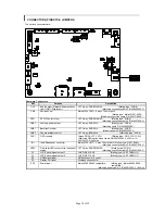
Page 10: ...cable P N 426058300 3 CNB3 Panel backlight control JST 2 way B2B XH A Matching type XHP 2 CNC1 OSD controls Hirose DF13A 12P 1 25H Mating type DF13 12S 1 25C Matching OSD switch mount cable P N 426122200 3 150mm or 426122210 3 250mm IR1 Infra Red sensor connector Molex 53261 0371 3 way 1 25mm pitch Mating type 51021 0300 Matching connection cable P N 426031500 3 LED1 Dual color LED connector for c...

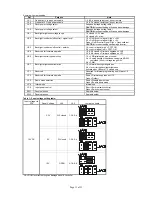
Page 11: ...JB4 Reserved for firmware upgrade 1 3 2 4 closed Firmware upgrade on U10 3 5 4 6 closed Firmware upgrade on U15 JB5 Backlight control type selection 1 2 VR Digital switch mount control 3 4 Analog backlight brightness control via RS 232 command 0xe0 voltage range 0 5V 5 6 PWM JB7 Backlight brightness orientation 1 2 Normal backlight brightness 3 4 Invert for the backlight brightness Activate when J...

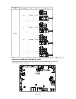
Page 12: ... 2 4 12V 12V closed 3 5 4 6 24VDC 18V 18V closed 3 5 4 6 Please make sure the backlight inverter must support 24V supply Because CNA1 pin 1 and CNB1 pin 2 will output 24VDC if input 24VDC via PP2 JA3 JA6 location on board Please pay attention to the jumper settings on JA3 JA6 which are red in color on board JA3 JA6 ...

Page 13: ...ved 8 Motion compensation mode OFF Enable for film mode a ON Disable for static text mode b Remark a Film mode Image with motion pattern b Static text mode Image with static pattern DIP Switch selection SW4 For 120Hz panel solution Use firmware revision U15 V0 02 00 or later Pos 1 Pos 2 Pos 3 Pos 4 Description Panel resolution For WUXGA panel OFF OFF OFF OFF NEC NL192120AC25 02 120Hz 1920x1200 ON ...

Page 14: ...acklight inverter connector JST S5B XH A Matching type XHP 5 PIN SYMBOL DESCRIPTION 1 GND Ground 2 VBKL Backlight power supply 12VDC 24V DC 3A max 3 BLCTRL Backlight On Off control signal refer to JB2 JB3 4 BVR_WIP Backlight brightness VR pin WIP 5 BVR_A Backlight brightness VR pin A CNB3 Panel backlight control JST 2 way B2B XH A Matching type XHP 2 PIN DESCRIPTION 1 Ground 2 Backlight status con...

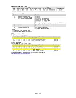
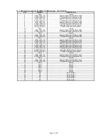
Page 15: ...B4 15 LVDS_OUT2_B4 Positive differential LVDS data bit B4 16 GND Ground 17 LVDS_OUT2_A0 Negative differential LVDS data bit A0 18 LVDS_OUT2_A0 Positive differential LVDS data bit A0 19 LVDS_OUT2_A1 Negative differential LVDS data bit A1 20 LVDS_OUT2_A1 Positive differential LVDS data bit A1 21 LVDS_OUT2_A2 Negative differential LVDS data bit A2 22 LVDS_OUT2_A2 Positive differential LVDS data bit A...

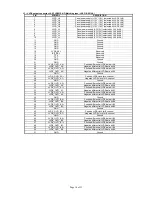
Page 16: ... LVDS_OUT1_A3 Negative differential LVDS data bit A3 26 GND Ground 27 LVDS_OUT1_AC Positive LVDS clock for A channel 28 LVDS_OUT1_AC Negative LVDS clock for A channel 29 GND Ground 30 LVDS_OUT1_A2 Positive differential LVDS data bit A2 31 LVDS_OUT1_A2 Negative differential LVDS data bit A2 32 LVDS_OUT1_A1 Positive differential LVDS data bit A1 33 LVDS_OUT1_A1 Negative differential LVDS data bit A1...

Page 17: ... Data Line for DDC 17 CEC GND Ground 18 5V 5 V Power max 50 mA 19 HPDET Hot Plug Detect P4 Display Port input PIN SYMBOL DESCRIPTION 1 ML_Lane 0 p Lane 0 positive 2 GND Ground 3 ML_Lane 0 n Lane 0 negative 4 ML_Lane 1 p Lane 1 positive 5 GND Ground 6 ML_Lane 1 n Lane 1 negative 7 ML_Lane 2 p Lane 2 positive 8 GND Ground 9 ML_Lane 2 n Lane 2 negative 10 ML_Lane 3 p Lane 3 positive 11 GND Ground 12 ...

Page 18: ...ottom of PCB if mounting on a metal plate we also recommend a layer of suitable insulation material is added to the mounting plate surface 10mm above the components 3 5mm around the edges Any of the holes shown above can be used for mounting the PCB they are 3 2mm in diameter CAUTION Ensure adequate insulation is provided for all areas of the PCB with special attention to high voltage parts such a...

Page 19: ...on CNA1 pin 1 and CNB1 pin 2 is 3A 24V 3A 12V Enable This is a pin provided on some inverters for On Off function and is used by this panel controller for VESA DPMS compliance If the inverter does not have an enable pin or the enable pin is not used then DPMS will not be operational Pin 3 should be matched to the inverters specification for the enable or disable pin CNB1 PIN DESCRIPTION 3 Enable F...

Page 20: ...er The main power load for On Off is handled by a relay on the controller Example for circuit design Signal description Notes 1 R1 470ohm on board 2 RPOT is an external potentiometer in line dip style that can be plugged directly into CNC1 pins 3 4 5 RPOT must be supplied installed by user 3 BVR_B Voltage tapped from top of potentiometer the node of R1 and RPOT 4 BVR_WIP Voltage tapped from wiper ...

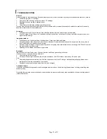
Page 21: ...rlaced mode will probably cause the image to be the wrong size to scroll flicker badly or possibly even no image Incorrect jumper settings on the controller may cause everything from total failure to incorrect image CAUTION Do not set the panel power input incorrectly Sparkling on the display faulty panel signal cable Backlight Items to check include Power input Controls Inverter and Tubes general...

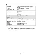
Page 22: ...ort Graphics OSD icons VESA DPMS implementation Yes Plug Play VESA DDC 1 2 b compatible Voltage output for LCD 3 3V 5V 12V 18V The current drawn for 18V panel from 24VDC power input is limited to 2A The current drawn for 3 3V 5V or 12V panel from 12V 24VDC power input is limited to 3A Output power from CN1 Audio output Stereo with amplication from HDMI Display port 2W x 2 channels V 5v RL 4ohm Inp...

Page 23: ...84 28 1 50 720p60 1280x720P 60Hz 74 25 45 60 576p50 720x576P 50Hz 26 9568 31 2 50 480p60 720x480P 60Hz 26 9568 31 4 60 Display Port P4 port Mode Resolution Clk MHz Horizontal freq KHz Vertical freq Hz T_70 720x400 70Hz 28 322 31 469 70 087 V_60 640x480 60Hz 25 175 31 469 59 940 SV_60 800x600 60Hz 40 000 37 879 60 317 X_60 1024x768 60Hz 65 000 48 363 60 004 SX_60 1280x1024 60Hz 108 63 81 60 020 UX_...

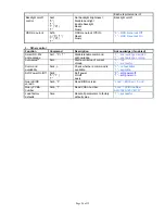
Page 24: ...ivalent Right button 0xfc Right button pressed Button equivalent Left button 0xfd Left button pressed Button equivalent 2 Parameter setting immediate relative reset and query Function Command Description Acknowledge if enabled Volume control on off mute 0x80 m M 0 1 r R Disable audio output Enable audio output Reset Query 0 audio off muted 1 audio on Volume control Audio Output 0x80 s S 0 1 r R En...

Page 25: ... defined RGB values 1 4200K 2 5000K 3 6500K 4 7500K Default 5 9300K Red level for selected colour temperature 0xb4 nn r R Set the level of the red channel for the selected colour temp value increment decrement Reset Query Red level for selected colour temperature Range 0 0 6 4 Default 6 4 Green level for selected colour temperature 0xb5 nn r R Set the level of the green channel for the selected co...

Page 26: ... 0xc1 0 1 Disable enable command acknowledge 0 acknowledge disabled 1 acknowledge enabled Auto setup 0xc3 Start auto setup of current vmode 0 fail 1 successful Command availability 0xc4 n Check whether a command is available 0 not available 1 available Soft Power On Off 0xc8 0 1 Soft power On off query 0 soft power off 1 soft power on Query BIOS version 0xcb 0 Read BIOS version nnnn BIOS ver nn nn...

Page 27: ...3 3 0x44 D 0x64 d 0x34 4 0x45 E 0x65 e 0x35 5 0x46 F 0x66 f 0x36 6 0x47 G 0x67 g 0x37 7 0x48 H 0x68 h 0x38 8 0x49 I 0x69 i 0x39 9 0x4A J 0x6A j 0x4B K 0x6B k 0x4C L 0x6C l 0x4D M 0x6D m 0x4E N 0x6E n 0x4F O 0x6F o 0x50 P 0x70 p 0x51 Q 0x71 q 0x52 R 0x72 r 0x53 S 0x73 s 0x54 T 0x74 t 0x55 U 0x75 u 0x56 V 0x76 v 0x57 W 0x77 w 0x58 X 0x78 x 0x59 Y 0x79 y 0x5A Z 0x7A z ...

Page 28: ...Contrast RGB Color Input Source HDMI Displayport Power States On Standby Sleep On mode Always on Display No sync message and never goes off when no signal Standby mode Off backlight Off panel power when no signal Reduced power off Sleep mode Screen saver on Always On Screen saver off Backlight off Display No sync message for 10sec then off backlight ...

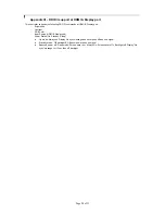
Page 29: ...Page 29 of 35 Appendix IV Mapping definition Definition of Mapping A ...

Page 30: ...Page 30 of 35 Definition of Mapping B ...

Page 31: ...Page 31 of 35 Definition of VESA ...

Page 32: ...Page 32 of 35 Definition of JEIDA ...

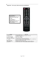
Page 33: ... Use button to direct control the hotkey function for switching to next input source In OSD menu pressing this button to adjust the settings DISPLAY BUTTON Activate the OSD menu display on screen STOP VGA BUTTON Press this button in the non OSD menu display mode to select VGA source HDMI BUTTON Press this button in the non OSD menu display mode to select DVI source P N 559000106 3 DigitalView remo...

Page 34: ...warranties of merchantability and fitness for a particular application or purpose The stated express warranties are in lieu of all obligations or liabilities on the part of the manufacturer for damages including but not limited to special indirect consequential damages arising out of or in connection with the use of or performance of the products CAUTION Whilst care has been taken to provide as mu...

Page 35: ...w com EUROPE Digital View Ltd The Lake House Knebworth Park Herts SG3 6PY UK Tel 44 0 20 7631 2150 Fax 44 0 20 7631 2156 Sales uksales digitalview com USA Digital View Inc 18440 Technology Drive Building 130 Morgan Hill California 95037 USA Tel 1 408 782 7773 Fax 1 408 782 7883 Sales ussales digitalview com WEBSITE www digitalview com Specifications subject to change without notice 2nd issue 5 Jun...

Reviews: