Page 17 of 35
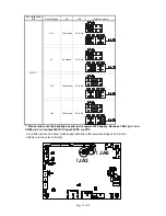
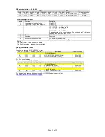
LED1 – Dual color LED connector for controller status, JST 3-way, S3B-ZR-SM4A (Mating type : JST ZHR-3)
PIN DESCRIPTION
1
Green LED pin (anode)
2
LED pin common (cathode)
3
Red LED pin (anode)
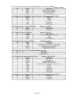
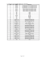
P3 – HDMI connector
PIN SYMBOL
DESCRIPTION
1 DATA2+
TMDS
Data2+
2
DATA2S
TMDS Data2 Shield
3 DATA2-
TMDS
Data2–
4 DATA1+
TMDS
Data1+
5
DATA1S
TMDS Data1 Shield
6 DATA1-
TMDS
Data1–
7 DATA0+
TMDS
Data0+
8
DATA0S
TMDS Data0 Shield
9 DATA0-
TMDS
Data0–
10 CLK+
TMDS
Clock+
11
CLK@
TMDS Clock Shield
12 CLK-
TMDS
Clock–
13 CEC
CEC
14 NC
No
connection
15
SCL
SCL (I²C Serial Clock for DDC)
16
SDA
SDA (I²C Serial Data Line for DDC)
17 CEC/GND
Ground
18
+5V
+5 V Power (max 50 mA)
19
HPDET
Hot Plug Detect
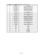
P4 – Display Port input
PIN SYMBOL
DESCRIPTION
1
ML_Lane 0 (p)
Lane 0 (positive)
2 GND
Ground
3
ML_Lane 0 (n)
Lane 0 (negative)
4
ML_Lane 1 (p)
Lane 1 (positive)
5 GND
Ground
6
ML_Lane 1 (n)
Lane 1 (negative)
7
ML_Lane 2 (p)
Lane 2 (positive)
8 GND
Ground
9
ML_Lane 2 (n)
Lane 2 (negative)
10
ML_Lane 3 (p)
Lane 3 (positive)
11 GND
Ground
12
ML_Lane 3 (n)
Lane 3 (negative)
13
CONFIG1
connected to Ground
1)
14
CONFIG2
connected to Ground
1)
15
AUX CH (p)
Auxiliary Channel (positive)
16 GND
Ground
17
AUX CH (n)
Auxiliary Channel (negative)
18
Hot Plug
Hot Plug Detect
19 GND
Ground
20
DP_PWR
Power for connector (3.3 V 500 mA)
PP2 - Power supply (Mating type : Molex 43645-0200 compatible)
PIN DESCRIPTION
1
+12VDC 5A max / +24VDC 5A max
2 Ground

