Digital Projection
E-Vision 6500 Series
Control Connections
Connection Guide
18
Rev D July 2014
Control Connections
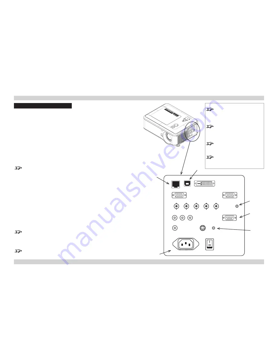
Screen Trigger
The Trigger output can be connected to an electrically operated screen, automatically
deploying the screen when the projector is switched on, and retracting the screen when the
projector is switched to standby.
USB Service Port
The USB Service Port is used to download firmware updates, issued from time to time by
Digital Projection.
Wired Remote Control
If infrared signals from the remote control cannot reach the projector due to excessive
distance or obstructions such as walls or cabinet doors, you can connect an external IR
repeater to the Remote Control input, and position its IR sensor within range of the operator.
Note that plugging in the remote control cable will disable the infra-red.
RS232
All of the projector’s features can be controlled via a serial connection, using the control
strings described in the
Remote Communications Guide
.
LAN
•
All of the projector’s features can be controlled via a LAN connection, using the industry
standard
PJLInk
commands. The PJLink specification can be downloaded from
http://pjlink.jbmia.or.jp/english
- click on the
Specifications
link.
•
The LAN IP Address of the projector can be set by using the
Network
submenu, which
can be found in the
Advanced Setting
submenu in the
Installation
menu.
•
Once the LAN IP Address has been set, it is possible to assign a
Host Name
and
Domain Name
to the projector, and to set up an
Alert Mail
address and
PJLink
password.
For more information about these settings, see
PJLink
in the
Remote
Communications Guide
.
•
A number of basic picture and input settings can be controlled directly using the
embedded
LAN Control utility
.
For full details of how to use this feature, see
LAN Control Utility
in the
Remote
Communications Guide
.
Notes
For a complete listing of pin
configurations for all signal and
control connectors, see
Wiring
Details
later in this Guide.
Only one remote connection can
be used at any one time. For more
information, see the
Installation
menu
in the
Operating Guide
.
For full details of how to use the
menu system, see the
Operating
Guide
.
When Standby Mode is set to
Eco
:
the
RS232
connection is disabled.
LAN
USB
RS232
SCREEN
TRIGGER
MAINS
LENS SHIFT
ZOOM
–
FOCUS
+
MENU
ENTER
RETURN
SOUR
CE
POW
ER
WARNING
LAMP1
LAMP2
AU
TO
WIRED
REMOTE
CONTROL


