


ZL0067-0B
PAGE 15
©2011 Veris Industries USA 800.354.8556 or +1.503.598.4564 / [email protected]
03112
Alta Labs, Enercept, Enspector, Hawkeye, Trustat, Veris, and the Veris ‘V’ logo are trademarks or registered trademarks of Veris Industries, L.L.C. in the USA and/or other countries.
TM
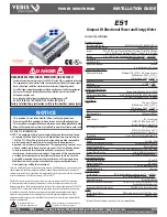
E51
INSTALLATION GUIDE
DATA LOGGING (E51C3 ONLY)
The E51C3 includes a data logging feature that records 10 meter parameters, each in
its own buffer.
Configuration.
Use register 150 to set the data logging time subinterval. Writing to the storage
buffer is triggered by the subinterval timer. The default subinterval is 15 minutes (at a
15 minute interval setting, the buffers hold 60 days of data). An external timer can be
used over Modbus by setting this register to 0.
Use register 159 to turn on data logging and select either Single Shot or Continuous
mode. (default is data logging on, Continuous mode). In Single Shot mode, the meter
records data until the buffer is full. When the buffer is full, the meter stops recording
new readings. Data for this time period is kept, but newer energy information is lost.
In Continuous mode, the meter continues to record energy data as long as the meter
is operating. The buffer can only hold 5760 entries at one time, however, so when
the number of records exceeds 5760, the oldest entry is deleted to make room for the
newest.
Registers 169-178 contain the pointers to 10 data storage buffers. Each buffer is user-
configurable with the Modbus address of the 16-bit data output to be stored. 32-bit
data, such as floating point data or 32-bit integer energy accumulators, require two
buffers. However, the lower 16 bits of an integer energy accumulator can be stored in
a single buffer (optional).
When the E51C3 is first installed, the buffers contain QNAN data, with a value of
0x8000. This data is considered invalid. If the buffer is reset at any point, all entries
in the buffers are overwritten with this 0x8000 value, indicating that it is invalid. All
invalid data is overwritten as the meter fills the buffer with new data entries.
Reading Data.
Use register 158 to choose which buffer to read. When this register value is set to
0, the meter is in data logging mode. Changing this value from 0 to (1 through 10)
switches the meter to reading mode and selects a buffer to read. Data from the
selected buffer appears in registers 8000 to 13760.
Read/Write Collision.
If the demand sub-interval timeout occurs while the user is reading a page (register
158 ≠ 0), the log data will be held in RAM until the next demand subinterval. At that
time, both the saved data from the previous cycle and the new data will be written
to the log, whether the page register has been set back to 0 or not. Error bits in the
Log Status Register (160) track these conditions. Subsequent log writes will proceed
normally. Provided the log read is concluded in less time than the demand sub-
interval, this mechanism handles the occasional collision and prevents the user from
reading data as the buffer is being updated.
The Log Status Register has additional error flag bits that indicate whether logging
has been reset or interrupted (power cycle, etc.) during the previous demand sub-
interval, and whether the Real-Time Clock has been changed (re-initialized to default
date/time due to a power-cycle or modified via Modbus commands).
STANDARD MODBUS DEFAULT SETTINGS
Setting
Value
Modbus
Register
Setup Password
00000
–
Reset Password
00000
–
System Type
40 (3 + N) Wye
130
CT Primary Ratio (if CTs are
not included)
100A
131
CT Secondary Ratio
1V
132
PT Ratio
1:1 (none)
133
System Voltage
600 V L-L
134
Max. Theoretical Power
(Analog Output: full scale
(20mA or 5V))
104 kW
135
Display Mode
1 (IEEE units)
137
Phase Loss
10% of System Voltage (60V), 25%
Phase to Phase Imbalance
142, 143
Pulse Energy
1 (kWh/pulse)
144
Demand: number of sub-
intervals per interval
1 (block mode)
149
Demand: sub-interval length
900 sec (15 min)
150
Modbus Address
001
–
Modbus Baud Rate
19200 baud
–
Modbus Parity
None
–
Log Read Page
0
158
Logging Configuration
Register
0
159
Log Register Pointer 1
3 (Import Real Energy MSR)
169
Log Register Pointer 2
4 (Import Real Energy LSR)
170
Log Register Pointer 3
5 (Export Real Energy MSR)
171
Log Register Pointer 4
6 (Export Real Energy LSR)
172
Log Register Pointer 5
29 (Real Demand)
173
Log Register Pointer 6
30 (Reactive Demand)
174
Log Register Pointer 7
31 (Apparent Demand)
175
Log Register Pointer 8
155 (Month/Day)
176
Log Register Pointer 9
156 (Year/Hour)
177
Log Register Pointer 10
157 (Minutes/Seconds)
178


