


ZL0067-0B
PAGE 3
©2011 Veris Industries USA 800.354.8556 or +1.503.598.4564 / [email protected]
03112
Alta Labs, Enercept, Enspector, Hawkeye, Trustat, Veris, and the Veris ‘V’ logo are trademarks or registered trademarks of Veris Industries, L.L.C. in the USA and/or other countries.
TM
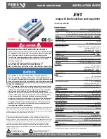
E51
INSTALLATION GUIDE
INSTALLATION
Disconnect power prior to installation.
Any covers that may be displaced during the installation
must be reinstalled before powering the unit.
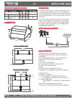
Mount the meter in an appropriate electrical enclosure
near equipment to be monitored.
Do not install on the load side of a Variable Frequency Drive
(VFD), aka Variable Speed Drive (VSD) or Adjustable Frequency
Drive (AFD).
Observe correct CT orientation.
The meter can be mounted in two ways: on standard 35 mm DIN rail or screw-
mounted to the interior surface of the enclosure.
A. DIN Rail Mounting
1. Attach mounting clips to the underside of the housing by sliding them into the
slots from the inside. The stopping pegs must face the housing, and the outside
edge of the clip must be flush with the outside edge of the housing.
2. Snap the clips onto the DIN rail. See diagram of the underside of the housing
(below).
Clip flush with
outside edge
Snap onto
DIN rail
Insert clips from inside
3. To prevent horizontal shifting across the DIN rail, use two Veris AV02 end stop clips.
B. Screw Mounting
1. Attach the mounting clips to the underside of the housing by sliding them into the
slots from the outside. The stopping pegs must face the housing, and the screw
hole must be exposed on the outside of the housing.
2. Use three #8 screws (not supplied) to mount the meter to the inside of the
enclosure. See diagram of the underside of the housing (below).
Screw holes
exposed for
mounting
Insert clips from outside
PRODUCT DIAGRAM
Alarm
Energy
kWh
1234.5
Two 5-character rows
of display text.
Top row alphanumeric;
Bottom row numeric only
The red Alarm LED lights when
any of the 3 phase voltages
drop below the selected thresh-
old. The green Energy LED lights
momentarily each time the
Energy output pulse is active.
CONTROL POWER
0.1A 50/60 Hz
A
B
C
N
1
2
A
B
C
Alarm
Energy
NC
NO
+ - S
OUTPUT
Common - 1 or 1/3 VAC Input
-
+
-
+
-
+
IA
IB
IC
Phase L
oss
Alarm
Pulse
Modbus
Shield
VA
VB
VC
Neutr
al
Ear
th
Con
trol
Po
we
r
UL: 90V
L-N
- 600V
L-L
CE: 90V
L-N
- 300V
L-N
VOLTAGE INPUTS
CAT III 50/60 Hz
+
–


