


ZL0067-0B
PAGE 1
©2011 Veris Industries USA 800.354.8556 or +1.503.598.4564 / [email protected]
03112
Alta Labs, Enercept, Enspector, Hawkeye, Trustat, Veris, and the Veris ‘V’ logo are trademarks or registered trademarks of Veris Industries, L.L.C. in the USA and/or other countries.
TM
POWER MONITORING
INSTALLATION GUIDE
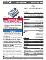
HAZARD OF ELECTRIC SHOCK, EXPLOSION, OR ARC FLASH
• Follow safe electrical work practices.
See NFPA 70E in the USA, or applicable local codes.
• This equipment must only be installed and serviced by qualified electrical personnel.
• Read, understand and follow the instructions before installing this product.
• Turn off all power supplying equipment before working on or inside the equipment.
• Any covers that may be displaced during the installation must be reinstalled
before powering the unit.
• Use a properly rated voltage sensing device to confirm power is off.
DO NOT DEPEND ON THIS PRODUCT FOR VOLTAGE INDICATION
Failure to follow these instructions will result in death or serious injury.
DANGER
NOTICE
• This product is not intended for life or safety applications.
• Do not install this product in hazardous or classified locations.
• The installer is responsible for conformance to all applicable codes.
• Mount this product inside a suitable fire and electrical enclosure.
FCC PART 15 INFORMATION
NOTE: This equipment has been tested by the manufacturer and found
to comply with the limits for a class B digital device, pursuant to part
15 of the FCC Rules. These limits are designed to provide reasonable
protection against harmful interference when the equipment is
operated in a residential environment. This equipment generates, uses,
and can radiate radio frequency energy and, if not installed and used
in accordance with the instruction manual, may cause harmful
interference to radio communications. Operation of this equipment in
a residential area may cause harmful interference in which case the
user will be required to correct the interference at his own expense.
Modifications to this product without the express authorization of
Veris Industries nullify this statement.
E51
Compact Bi-Directional Power and Energy Meter
Installer’s Specifications
Measurement Accuracy:
Real Power and Energy
IEC 62053-22 Class 0.5S, ANSI C12.20 0.5%
Reactive Power and Energy
IEC 62053-23 Class 2, 2%
Current
0.4% (+0.015% per °C deviation from 25°C) from 5% to 100% of range;
0.8%
(+0.015% per °C deviation from 25°C) from 1% to 5% of range
Voltage
0.4% (+0.015% per °C deviation from 25°C) from 90 V
L-N
to 600 VAC
L-L
Sample Rate
2520 samples per second, no blind time
Data Update Rate
1 sec
Type of Measurement
True RMS
One
to three phase AC system
Input Voltage Characteristics:
Measured AC Voltage
Minimum 90 V
L-N
(156 V
L-L
) for stated accuracy;
UL Maximums: 600 V
L-L
(347 V
L-N
)
CE
Maximums: 300 V
L-N
(520 V
L-L
)
Metering Over-Range
+20%
Impedance
2.5 MΩ
L-N
/5 MΩ
L-L
Frequency Range
45 to 65 Hz
Input Current Characteristics:
CT Scaling
Primary: Adjustable from 5 A to 32,000 A
Measurement Input Range
0 to 0.333 VAC or 0 to 1.0 VAC (+20% over-range)
Impedance
10.6 kΩ (1/3 V mode) or 32.1 kΩ (1 V mode)
Control Power:
AC
5 VA max.; 90V min.
UL Maximums: 600 V
L-L
(347 V
L-N
)
CE
Maximums: 300 V
L-N
(520 V
L-L
)
DC*
3 W max.; UL and CE: 125 to 300 VDC
Ride Through Time
100 msec at 120 VAC
Output:
Alarm Contacts
N.C., static output
(30VAC/DC,
100mA max. @ 25°C,
derate
0.56mA per °C above 25°C)
Real Energy Pulse Contacts
N.O., static output
(30 VAC/DC, 100 mA max. @ 25°C,
derate
0.56 mA per °C above 25°C)
RS-485 Port
2-wire, 1200 to 38400 baud, Modbus RTU
Mechanical Characteristics:
Weight
0.62 lb (0.28 kg)
IP Degree of Protection (IEC 60529)
IP40 front display; IP20 Meter
Display Characteristics
Back-lit blue LCD
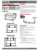
Terminal Block Screw Torque
0.37 ft-lb (0.5 N·m) nominal/0.44 ft-lb (0.6 N·m) max.
Terminal Block Wire Size
26 to 14 AWG (0.13 to 2.08 mm
2
)
Rail
T35 (35mm) DIN Rail per EN50022
Environmental Conditions:
Operating Temperature
-30° to 70°C
Storage Temperature
-40° to 85°C
Humidity Range
<95% RH (non-condensing)
Altitude of Operation
3 km max.
Metering Category:
US and Canada
CAT III; for distribution systems up to 347 V
L-N
/600 VAC
L-L
CE
CAT III; for distribution systems up to 300 V
L-N
Dielectric Withstand
Per UL 508, EN61010
Conducted and Radiated Emissions
FCC part 15 Class B, EN55011/EN61000 Class B
(residential
and light industrial)
Conducted and Radiated Immunity
EN61000 Class A (heavy industrial)
Safety:
US and Canada (cULus)
UL508 (open type device)/CSA 22.2 No. 14-05
Europe (CE) EN61010-1:2001
* External DC current limiting is required, see fuse recommendations.
RoHS
Compliant
For use in a Pollution Degree 2 or better environment only. A Pollution Degree 2 environment must
control conductive pollution and the possibility of condensation or high humidity. Consider the
enclosure, the correct use of ventilation, thermal properties of the equipment, and the relationship
with the environment. Installation category: CAT II or CAT III
Provide a disconnect device to disconnect the meter from the supply source. Place this device
in close proximity to the equipment and within easy reach of the operator, and mark it as the
disconnecting device. The disconnecting device shall meet the relevant requirements of IEC 60947-
1 and IEC 60947-3 and shall be suitable for the application. In the US and Canada, disconnecting
fuse holders can be used. Provide overcurrent protection and disconecting device for supply
conductors with approved current limiting devices suitable for protecting the wiring. If the
equipment is used in a manner not specified by the manufacturer, the protection provided by the
device may be impaired.
This symbol indicates an
electrical shock hazard exists.
Documentation must be consulted where
this symbol is used on the product.


