


ZL0067-0B
PAGE 7
©2011 Veris Industries USA 800.354.8556 or +1.503.598.4564 / [email protected]
03112
Alta Labs, Enercept, Enspector, Hawkeye, Trustat, Veris, and the Veris ‘V’ logo are trademarks or registered trademarks of Veris Industries, L.L.C. in the USA and/or other countries.
TM
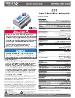
E51
INSTALLATION GUIDE
QUICK SETUP INSTRUCTIONS
These instructions assume the meter is set to factory defaults. If it has been
previously configured, all optional values should be checked.
1. Press the
+
+
or
–
button repeatedly until
SETUP
screen appears.
2. to the
PASWD
screen.
3. through the digits. Use the
+
+
or
–
buttons to select the password (the default
is
00000
). Exit the screen to the right.
4. Use the
+
+
or
–
buttons to select the parameter to configure.
5. If the unit has an RS-485 interface, the first Setup screen is
S COM
(set
communications).
a. to the
ADDR
screen and through the address digits. Use the
+
+
or
–
buttons to select the Modbus address.
b. to the
BAUD
screen. Use the
+
+
or
–
buttons to select the baud rate.
c. to the
PAR
screen. Use the
+
+
or
–
buttons to select the parity.
d. back to the
S COM
screen.
6.
–
to the
S CT
(Set Current Transducer) screen. If this unit does not have an RS-
485 port, this will be the first screen.
a. to the
CT V
screen. Use the
+
+
or
–
buttons to select the voltage
mode Current Transducer output voltage.
b. to the
CT SZ
screen and through the digits. Use the
+
+
or
–
buttons
to select the CT size in amps.
c. back to the
S CT
screen.
7.
–
to the
S SYS
(Set System) screen.
a. to the
SYSTM
screen. Use the
+
+
or
–
buttons to select the System
Type (see wiring diagrams).
b. back to the
S SYS
screen.
8. (Optional)
–
to the
S PT
(Set Potential Transformer) screen. If PTs are not used,
then skip this step.
a. to the
RATIO
screen and through the digits. Use the
+
+
or
–
buttons
to select the Potential Transformer step down ratio.
b. back to the
S PT
screen.
9.
–
to the
S V
(Set System Voltage) screen.
a. to the
VLL
(or VLN if system is 1L-1n) screen and through the digits.
Use the
+
+
or
–
buttons to select the Line to Line System Voltage.
b. back to the S V screen.
10. Use the to exit the setup screen and then
SETUP
.
11. Check that the wrench is not displayed on the LCD.
a. If the wrench is displayed, use the
+
+
or
–
buttons to find the
ALERT
screen.
b. through the screens to see which alert is on.
For full setup instructions, see the configuration instructions on the following pages.
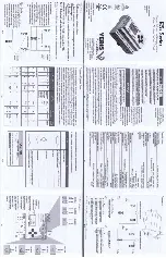
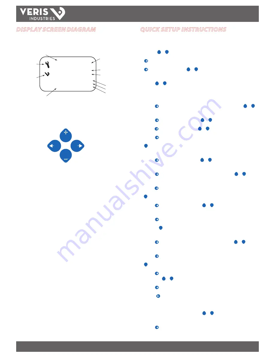
DISPLAY SCREEN DIAGRAM
Tx
Rx
ERR
♥
Screen Name or Units
Diagnostic Alert
Logo
Numeric Data
Alive Indicator
Transmit Data
Receive Data
Receive Data Error
LCD Screen:
Buttons:
+
–
(Up)
Select
(Right)
Next
(Down)
Select
(Left)
Back
Export
Import


