background image


JetBox-FloydSC User Manual rev 0.1 

www.diamondsystems.com


Page 26 

12. GETTING STARTED 

JetBox-FloydSC is shipped to our customers ready to work out of the box. A 12V DC adapter is included with the 
JetBox-FloydSC. The Jetson module, included with the JetBox-FloydSC is flashed with the latest BSP. However, 
it is highly recommended to check the Diamond System Corp website for any updated BSPs at 

http://www.diamondsystems.com/products/floydsc


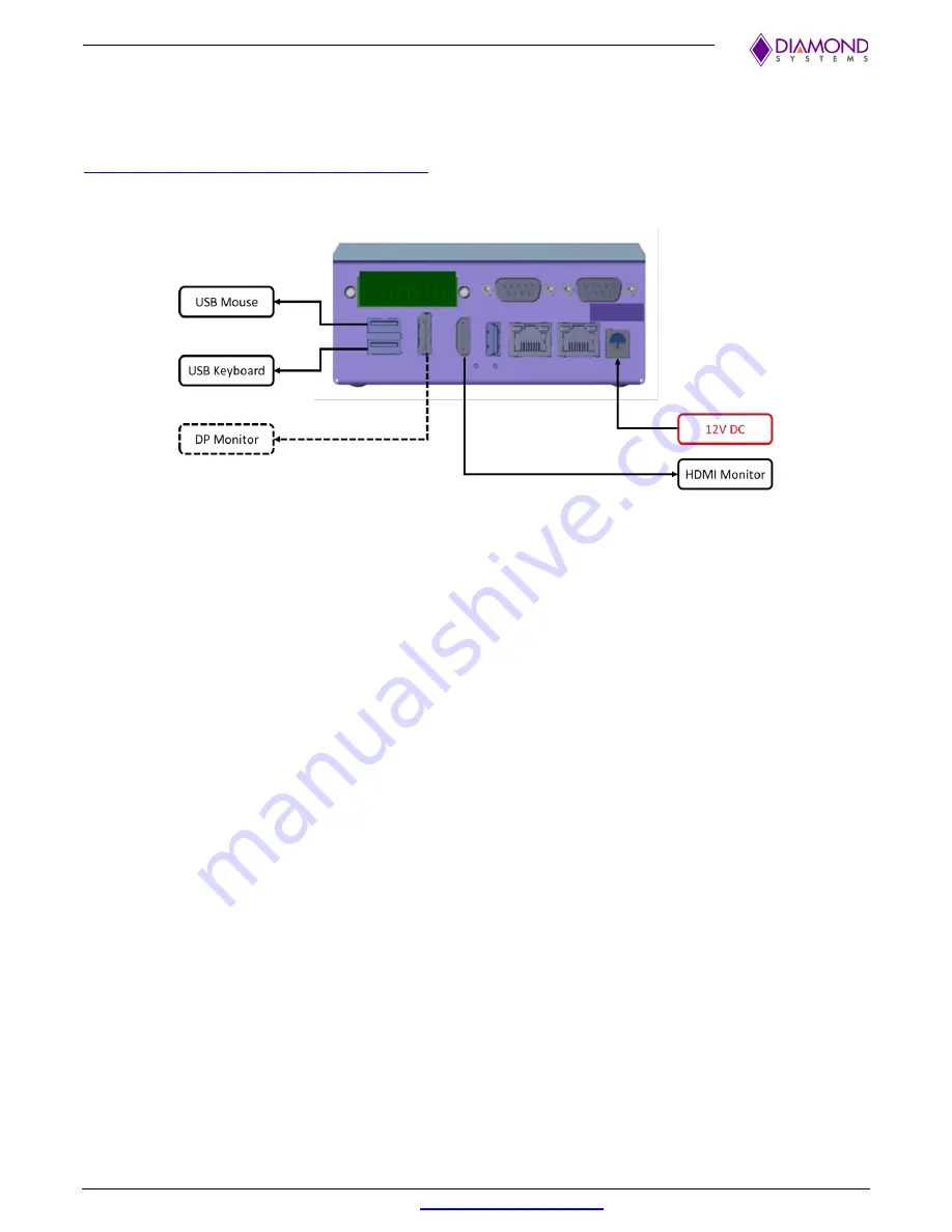
To get started with Jetbox-Floyd, a minimum of USB keyboard, USB mouse & an HDMI monitor are required. 
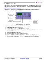
Refer to the reference set up image provided below: 


Figure 11 

JetBox-FloydSC Typical Set Up


Follow the steps provided below for Jetbox-Floyd connections and booting to OS: 

1.  Connect the included 12V DC IN on front panel 

2.  Connect the USB keyboard & mouse to USB2.0 ports on the front panel 

3.  Connect the HDMI monitor to HDMI port on the front panel. Alternatively, a DP monitor can also be used 

instead of an HDMI monitor. 

4.  Ensure that all the connections are intact 

5.  Power ON the adapter and the module should now boot to OS 

6.  On the Linux Welcome screen, fill in the basic details like Username, password, date & time 

7.  The system boots to Ubuntu Desktop. Now, the system is set up & ready for further development  


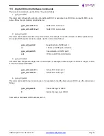
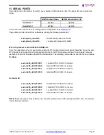
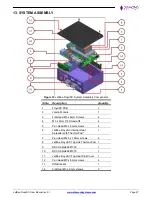
Summary of Contents for JB-FLDSC-NAO-02

Page 1: ...OYD SC NVIDIA Jetson Nano TX2 NX Xavier NX System User Manual PRELIMINARY Copyright 2022 Diamond Systems Corporation www diamondsystems com FOR TECHNICAL SUPPORT PLEASE CONTACT Email support diamondsy...

Page 2: ...s 10 FloydSC Carrier board Callouts TOP 11 FloydSC Carrier board Callouts BOTTOM 11 7 Jumper Configuration 12 Digital I O Configuration 12 USB2 0 Top Port Host Device Selection 13 Serial Ports Configu...

Page 3: ...s 24 11 Serial Ports 25 12 Getting Started 26 13 System Assembly 27 Installing the Jetson Module on FloydSC 28 Installing FloydSC inside the JetBox 29 14 Reprogramming the Embedded Linux Image 30 Hard...

Page 4: ...cally impossible to detect because there is no visual sign of failure or damage In this type of damage the board eventually stops functioning because of some defective components Usually the failure c...

Page 5: ...Some common causes such as a metal screwdriver tip slipping or a screw dropping onto the board while it is powered up causes a short between a power pin and a signal pin on a component These faults ca...

Page 6: ...enclosure is DIN rail mountable or can be used in a tabletop scenario The system is compatible with both 12V and 24V DC power supplies A 12VDC universal AC adapter is included with the system System C...

Page 7: ...ith one or two Gigabit Ethernet ports 1 all models A 10 100 1000 Ethernet port routed from the module 2 NX model only A 10 100 1000 Ethernet port derived from the Intel WGI210IT Intel I210 PCIe Ethern...

Page 8: ...m with Nano module the Xavier NX modules There are two PCIe ports available on the Xavier NX module due to which either an additional Ethernet port can be supported or the Daughterboard Expansion Figu...

Page 9: ...ms com Page 9 5 MECHANICAL DRAWING 3D STEP Model The complete product 3D STEP model is available to our customers in the product support page here 2D Drawing All dimensions are in mm Figure 3 JetBox F...

Page 10: ...DS JUMPER LOCATIONS JetBox FloydSC Front Panel Call Outs Figure 5 JetBox FloydSC Front Panel Call Outs Sl No Description 1 Power In 7 24 VDC 2 Ethernet 1 3 Ethernet 2 4 Reset Switch 5 Recovery Switch...

Page 11: ...FloydSC User Manual rev 0 1 www diamondsystems com Page 11 FloydSC Carrier board Callouts TOP Figure 6 FloydSC Carrier Board TOP FloydSC Carrier board Callouts BOTTOM Figure 7 FloydSC Carrier Board B...

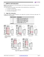
Page 12: ...guration 2 JP2 USB2 0 Top Port Host Device Selection 3 JP3 Serial Ports Configuration Digital I O Configuration Jumpers are provided to enable pull up down on the Digital I Os By default the DIOs are...

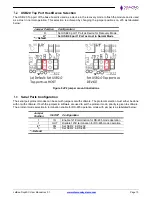
Page 13: ...s Host in Normal Mode Default Figure 9 JP2 jumper mount illustrations Serial Ports Configuration The serial port protocol modes can be set with jumpers or with software The protocol selection must eit...

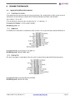
Page 14: ...minated on a standard vertical connector The connector follows standard HDMI pinout D2 1 2 D2 Shield D2 3 4 D1 D1 Shield 5 6 D1 D0 7 8 D0 Shield D0 9 10 Clock Clock Shield 11 12 Clock CEC 13 14 No Con...

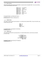
Page 15: ...w Connector Part No Link PP LPJG101AGNL 1 DSC Mating cable Standard LAN Cat6 cable USB2 0 Ports The system hosts two USB 2 0 ports accessible on a vertically stacked standard USB 2 0 Type A socket tha...

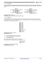
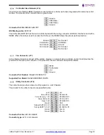
Page 16: ...Male DSC Mating cable Standard DB9 female to female cable Digital I O The system provides access to 8 digital I O pins on the front panel terminated on a 11 position 3 5mm pitch screw terminal connect...

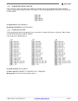
Page 17: ...the camera modules The pinouts are as specified below J15 J16 J14 1 GND_DIG 1 GND_DIG 1 GND_DIG 2 CSI0_D0_N 2 CSI2_D0_N 2 CSI4_D0_N 3 CSI0_D0_P 3 CSI2_D0_P 3 CSI4_D0_P 4 GND_DIG 4 GND_DIG 4 GND_DIG 5...

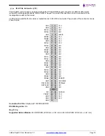
Page 18: ...4 3 3V PETn3 5 6 N C PETp3 7 8 N C GND 9 10 LED1 PERn3 11 12 3 3V PERp3 13 14 3 3V GND 15 16 3 3V PETn2 17 18 3 3V PETp2 19 20 N C GND 21 22 N C PERn2 23 24 N C PERp2 25 26 N C GND 27 28 N C PETn1 29...

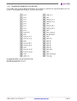
Page 19: ...FH55 40S 0 5SH DSC Mating Cable PN 6971400 1 Hi Vin 21 USB2_D_P 2 Hi Vin 22 GND 3 Hi Vin 23 USB_SS_TX_P 4 Hi Vin 24 USB_SS_TX_N 5 Hi Vin 25 GND 6 Hi Vin 26 USB_SS_RX_P 7 Hi Vin 27 USB_SS_RX_N 8 Hi Vin...

Page 20: ...t 5 No Connect Fan Connector J17 Active thermal solution is not part of the system However to support active solutions carrier board provides the provision for this with a fan connector The pinouts fo...

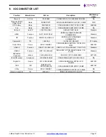
Page 21: ...21203 H7U0 4H VERTICAL DP STANDARD CONNECTOR Standard Camera x3 TE 1 84952 5 15 PIN FFC RA SMD FFC cable Serial Ports Pinrex 220 97 36GB01 CONN HEADER VERTICAL 10POS 2X5 2MM 6981075 USB 3 0 Foxconn UE...

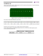
Page 22: ...Terminal Pin Numbering The pinouts of the screw terminals are as given below 1 2 3 4 5 6 7 8 9 10 11 DIO 0 DIO 1 DIO 2 DIO 3 DIO 4 DIO 5 DIO 6 DIO 7 3 3V or 5V Ground Ground The DIOs on the Floyd SC C...

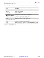
Page 23: ...ls 3 3V 5V configurable Pull resistors 10K ohms 1 Jumper selectable pull up down Input Voltage Thresholds Logic 0 0 5V min 0 99V 3 3V VIO 1 5V 5V VIO max Logic 1 2 64V 3 3V VIO 3 5V 5V VIO min 5 5V ma...

Page 24: ...t as an input DIO 5 earlier set as an output use the command as follows gpio_util getdir 2 read direction of GPIO port 2 in Prints out GPIO port 2 direction gpio_util getdir 5 read direction of GPIO p...

Page 25: ...it disable it thereafter Since the auto RTS feature is not supported on Nvidia serial port drivers the RTS signals would need to be enabled manually just before transmit disabled right after the trans...

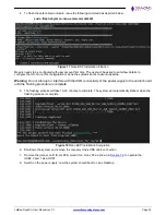
Page 26: ...or are required Refer to the reference set up image provided below Figure 11 JetBox FloydSC Typical Set Up Follow the steps provided below for Jetbox Floyd connections and booting to OS 1 Connect the...

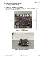
Page 27: ...Module 1 3 Flat Head M3 x 6mm Screws 4 4 M3 x 8mm F F Stand offs 4 5 Pan Head M3 x 6mm screws 4 6 JetBox FloydSC Internal Heat Spreader with Thermal Pad 1 7 Pan Head M2 5 x 10mm screws 4 8 JetBox Floy...

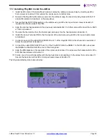
Page 28: ...talling FloydSC inside the JetBox Installing the Jetson Module on FloydSC 5 If not present on board install 4x M2 5 x 6 5mm long F F spacers on board using 4x M2 5 x 4mm pan head screws inserted from...

Page 29: ...mm at location 7 5 Remove the thermal line from the thermal pad and apply it on the heat spreader at location 8 6 Install the Screw Terminal PCB to the front panel of the enclosure using 2x M3 x 6mm p...

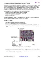
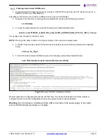
Page 30: ...ded utilities for camera connector interfaces J12 J13 and J14 3 Added USB2 0 port 1 Host mode support 4 Added utility for I2C GPIO expander 5 Added User LED control The Diamond Systems BSP is released...

Page 31: ...e file may be copied to a different source such as the Desktop Issue the following command to navigate to the directory containing the downloaded file cd Desktop 2 To unzip the copied Image file issue...

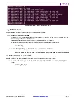
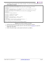
Page 32: ...to ubuntu desktop Warning Do not interrupt or interfere with the USB connectivity or the power supply to the carrier board until the flashing procedure is complete 5 The flashing process will take 15...

Page 33: ...y take a few minutes for the file to unzip NOTE The tar gz file name is liable to change according to the version and release date 4 To switch to the directory where the file has been extracted issue...

Page 34: ...ot when the flashing process is complete Figure 20 Xavier NX BSP Installation Completion 7 Shutdown the carrier board and remove the recovery mode USB cable connection 8 Remove the jumper on D from JP...

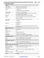
Page 35: ...2x USB 2 0 1x USB 3 0 Utility Force recovery Power button Reset Debug UART Force off I2C 3 3V SPI 3 3V Digital I O Specifications Device PCA9535PW Number of Lines 8 Direction Programmable bit by bit L...

Page 36: ...n the shipping document The Customer will prepay the shipment cost of the product to the Diamond Systems Corporation designated site Diamond Systems Corporation will prepay the return shipping cost of...

Reviews: