CC7574DKV OPERATOR’S MANUAL
6. When finished cutting, shut off water supply
to the blade guard, shut off water supply at
source and remove source hose from the
saw.
7.
Drain water from upper gearbox heat sink.
(
ref. maintenance instructions: upper
gearbox).
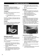
Water Pump (Optional)
The optional water pump directs water from the
water metering control valve to the saw blade.
1. Ensure all water supply lines are
connected.
2. Ensure that the water valves on the right
and left side of the saw are shut.
3. Turn on the water pump switch to start the
pump.
NOTE: DO NOT start the water pump until just
before cutting. DO NOT leave the water pump on
when the cutting task is complete to avoid draining
the battery.
4. Move the water valve lever on the right side
of the saw to the fully open position.
5. Increase or decrease water flow by
adjusting the left side water valve lever.
6. When cutting is complete, shut both water
valves.
7. Turn the water pump switch to
OFF
to stop
the pump.
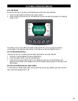
Automatic Water System (AWS)
The automatic water system provides a
solenoid in the water supply system that works
in conjunction with the “Zero Blade” option on
the control panel. When the saw blade is
“zeroed” at the pavement surface, the solenoid
valve will allow water to flow when the blade is
lowered into a cut. When the blade is raised
out of the cut and the blade passes the “zero”
point, the water flow will automatically shut off.
NOTE: When using AWS, adjust the water
valve lever to meter the water flow. AWS will
automatically turn the water on/off when the
blade enters or exits the cut.
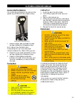
Cutting Guides
Use the cutting guides as needed to help
follow the cutting line. Always check the cutting
guides for proper alignment with the blade prior
to cutting.
Adjusting the Front Pointer
1. Remove the lanyard from the cable cleat.
2. Lower the front pointer frame to the ground.
3. Loosen both front pointer frame screws.
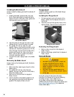
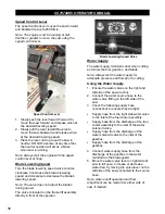
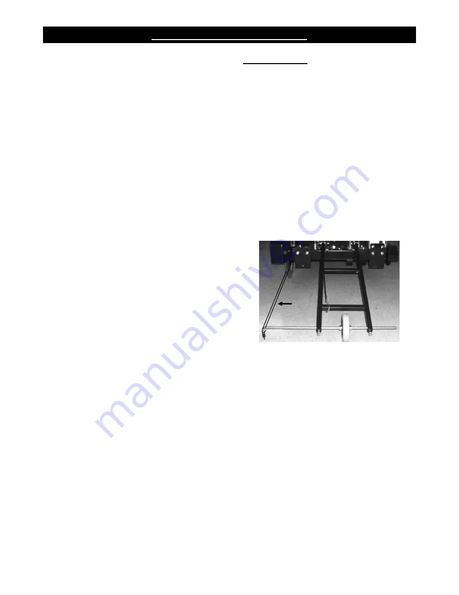
4. Divide an 8–10 ft piece of string in half.
5. Place the looped end of string into a gullet
on the backside of the blade.
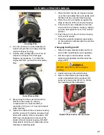
6. Place one string line up against the
backside of the blade and one string line up
against the front side of the blade. Holding
the string ends in one hand, tension the
lines out toward the front pointer rod.
Tensioned String Line
7. Adjust the pointer rod to place the tip
between the tensioned string lines.
8. Retighten both front pointer frame screws.
9. Lift the frame off the ground when finished.
10. Tension the lanyard and secure it to the
cable cleat.
Adjusting the Rear Pointer(s)
1. Loosen the rear pointer nut and screw on
the back of the frame base.
2. Adjust the orientation of the rear pointer rod
and retighten the screw and nut to secure.
37
Summary of Contents for CC7574DKV
Page 1: ...CORE CUT OPERATOR S MANUAL CC7574DKV CC7574DKV 3 MAY 2022 Part 1802742 01...
Page 2: ......
Page 11: ...CC7574DKV OPERATOR S MANUAL CC7574DKV Specifications 11...
Page 12: ...CC7574DKV OPERATOR S MANUAL CC7574DKV 3 Specifications 12...
Page 65: ...CC7574DKV OPERATOR S MANUAL Appendix B CC7574DKV RPM Chart CC7574DKV 3 RPM Charts 65...
Page 66: ...CC7574DKV OPERATOR S MANUAL 66...
Page 67: ...CC7574DKV OPERATOR S MANUAL CC7574DKV Blade Size Conversion Chart 67...
Page 68: ...CC7574DKV OPERATOR S MANUAL CC7574DKV 3 Blade Size Conversion Chart 68...
Page 71: ......


