MFC-CB™ Operation and Maintenance Manual
©2001~2007
DH Instruments, a Fluke Company
Page 4
1.2.5.2
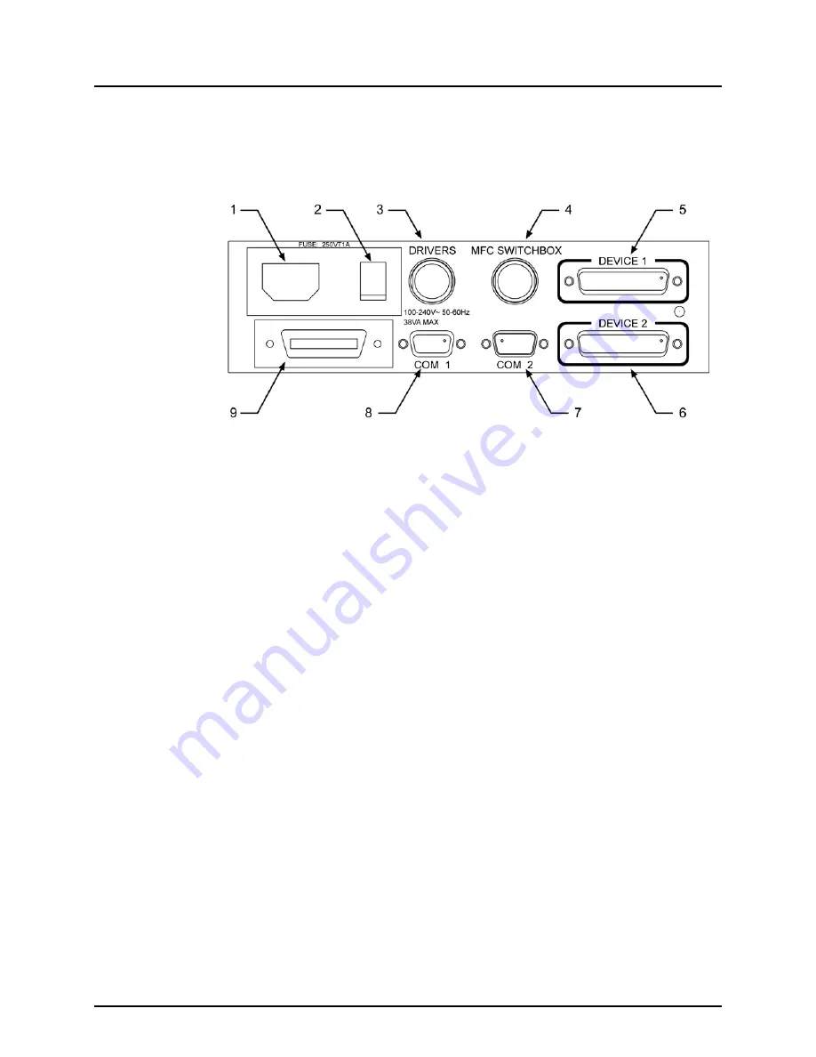
REAR PANEL
The rear panel assembly provides DEVICE1 and DEVICE2 analog input/output
channels, a 12 V drivers connection, communications interfaces and the power
connection module.
1. Electrical power connector (IEC60320)
2. Power ON/OFF switch
3. Connector for 12V DRIVERS
4. Connector for MFC Switchbox control
5. DEVICE1 electrical input/output connection
6. DEVICE2 electrical input/output connection
7. COM2 connection for pass through communication
8. COM1 connection for host computer
9. IEEE-488 connection for host computer
Figure 2.
MFC-CB Rear Panel


