background image

English

8

Cleaning


WARNING:

 Blow dirt and dust out of all air vents with 

clean, dry air at least once a week. To minimize the risk 
of eye injury, always wear ANSI Z87.1 approved eye 
protection when performing this procedure.


WARNING:

 Never use solvents or other harsh 

chemicals for cleaning the non‑metallic parts of the 
tool. These chemicals may weaken the plastic materials 
used in these parts. Use a cloth dampened only with 
water and mild soap. Never let any liquid get inside the 
tool; never immerse any part of the tool into a liquid.

MAINTENANCE


WARNING: To reduce the risk of serious personal 

injury, turn unit off and remove the battery pack 

before making any adjustments or removing/

installing attachments or accessories.

 An 

accidental start‑up can cause injury.

Your 

D

e

WALT

 power tool has been designed to operate 

over a long period of time with a minimum of maintenance. 
Continuous satisfactory operation depends upon proper tool 
care and regular cleaning.


WARNING:

 Keep the rotating string roughly parallel 

with the ground (tilted no more than 30

°

). This trimmer 

is not an edger. DO NOT TILT the trimmer so that the 
string is spinning near a right angle to the ground. 
Flying debris can cause serious injury.

Bump Feed Trimmer Line Feed

Your trimmer uses 0.08" (2.0 mm) diameter nylon line. 
Cutting line will wear faster and require more feeding if the 
cutting is done along sidewalks or other abrasive surfaces or 
heavier weeds are being cut.
As you use the trimmer, the string will get shorter due to 
wear. Gently bump the trimmer on the ground while running 
at normal speed and the line will feed.

nOTE:

 Extending nylon line beyond the 17" (432 mm) swath 

will negatively affect performance, runtime, and the life of 
the trimmer due to potential of damaging motor. Doing so 
may void the warranty.

Helpful Cutting Tips

•  Use the tip of the string to do the cutting; do not force 

string head into uncut grass.

•  Wire and picket fences cause extra string wear, even 

breakage. Stone and brick walls, curbs, and wood may 
wear string rapidly.

•  Do not allow spool cap to drag on ground or 

other surfaces.

•  In long growth, cut from the top down and do not 

exceed 12" (300 mm) high.

•  Keep trimmer tilted toward the area being cut; this is the 

best cutting area.

•  The trimmer cuts when passing the unit from the left to 

right. This will avoid throwing debris at the operator.

•  Avoid trees and shrubs. Tree bark, wood moldings, siding, 

and fence posts can easily be damaged by the string.
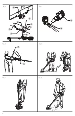
Trimming (Fig. E–G)

With the string trimmer on, angle it and swing side to side as 
shown in Fig. E, F.
Maintain a minimum distance of 24" (610 mm) between the 
guard and your feet as shown in Fig. G.


WARNING:

 Hold the tool using only the designated 

gripping surfaces: The powerhead handle and the 
auxiliary handle. 


WARNING:

 Do not use the pole as a gripping surface.

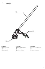
Proper hand position requires one hand on the powerhead 
handle 

 11 

 and one hand on the auxiliary handle 

 12 

.

Proper Hand Position (Fig. D, E)


WARNING: 

To reduce the risk of serious personal injury, 

ALWAYS

 use proper hand position as shown.


WARNING:

 To reduce the risk of serious personal 

injury, 

ALWAYS

 hold securely in anticipation of a 

sudden reaction.

OPERATION


WARNING: To reduce the risk of serious personal 

injury, turn unit off and remove the battery pack 

before making any adjustments or removing/

installing attachments or accessories.

 An 

accidental start‑up can cause injury.

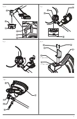
Assembling the Guard (Fig. C)

1.  Slide the guard 

 2 

 into place as shown in Fig. C.

2.  Secure with the guard screws and washers 

 13 

 and 

washers, tighten securely.

Assembling the String Trimmer 

Attachment to the Powerhead (Fig. A, B)

1.  The upper powerhead pole 

 5 

 is equipped with three 

latching holes 

 8 

 9 

 10 

,for the latching button 

 6 

2.  When installing the string trimmer attachment 

 1 

 into 

the upper powerhead pole 

 5 

, use the arrows 

 7 

 to align 

the latching button

 6 

 with latching hole 

 8 

, as shown 

in Fig. B. 

nOTE:

 To properly engage the latching button

 6 

 with 

the latching hole 

 8 

, slightly rotate the powerhead 

pole 

 5 

 and move it axially until the latching button 

engages the latching hole.  

DO nOT

 insert the latching button into latching 

hole 

 9 

, or 

 10 

. Doing so will position the string trimmer 

attachment in an incorrect orientation which could 
create a safety hazard. Latching holes  

 9 

 and 

 10 

 are for 

other attachments.

3.  Turn the knob 

 4 

 to secure the attachment.

4.  When properly assembled, it should look like Fig. B. If 

it does not, do not use, disassemble and re-align the 
string trimmer attachment 

 1 

 so the latching button 

 6 


engages with latching hole 

 8 

 as shown in Fig B.

nOTE: 

Ensure the attachment is fully engaged and the 

knob is fully tightened before operating. Check for proper 
engagement and tightness during use.

Summary of Contents for DWOAS9ST

Page 1: ...e question ou tout commentaire nous contacter Si tiene dudas o comentarios contáctenos 1 800 4 DeWALT DWOAS9ST String Trimmer Attachment Accessoire Taille Bordure Conexión de Podadora de Cuerda Instruction Manual Guide D utilisation Manual de instrucciones ...

Page 2: ...English original instructions 4 Français traduction de la notice d instructions originale 11 Español traducido de las instrucciones originales 20 ...

Page 3: ... Components 1 String trimmer pole 2 Guard 3 Spool housing 1 2 3 Composants 1 Manche du taille bordure 2 Protecteur 3 Boîtier de la bobine Componentes 1 Poste de podadora de cuerda 2 Protección 3 Alojamiento de carrete ...

Page 4: ...2 Fig B Fig C Fig D Fig E Fig F Fig G 24 610 mm 2 13 9 6 5 7 10 1 7 8 4 11 12 ...

Page 5: ...3 Fig H Fig I Fig J Fig K 3 24 18 19 20 21 23 19 22 Fig L 14 14 15 381 mm 15 17 17 432 mm 16 2 13 15 25 27 26 2 ...

Page 6: ...oting and balance at all times This enables better control of the power tool in unexpected situations f Dress properly Do not wear loose clothing or jewelry Keep your hair clothing and gloves away from moving parts Loose clothes jewelry or long hair can be caught in moving parts GENERAL POWER TOOL SAFETY WARNINGS WARNING Read all safety warnings instructions illustrations and specifications provid...

Page 7: ...re these are connected and properly used Use of dust collection can reduce dust related hazards h Do not let familiarity gained from frequent use of tools allow you to become complacent and ignore tool safety principles A careless action can cause severe injury within a fraction of a second 4 Power Tool Use and Care a Do not force the power tool Use the correct power tool for your application The ...

Page 8: ... in a dry location only Do not allow the appliance to become wet Do not immerse the appliance in water Do not open the body casing There are not user serviceable parts inside Do not operate the appliance in explosive atmospheres such as in the presence of flammable liquids gases or dust b Never allow children or people unfamiliar with these instructions to use the machine Local regulations can res...

Page 9: ...ditional Safety Information WARNING Never modify the power tool or any part of it Damage or personal injury could result WARNING ALWAYS use safety glasses Everyday eyeglasses are NOT safety glasses Also use face or dust mask if operation is dusty ALWAYS WEAR CERTIFIED SAFETY EQUIPMENT ANSI Z87 1 eye protection CAN CSA Z94 3 ANSI S12 6 S3 19 hearing protection NIOSH OSHA MSHA respiratory protection...

Page 10: ...mmer cuts when passing the unit from the left to right This will avoid throwing debris at the operator Avoid trees and shrubs Tree bark wood moldings siding and fence posts can easily be damaged by the string Trimming Fig E G With the string trimmer on angle it and swing side to side as shown in Fig E F Maintain a minimum distance of 24 610 mm between the guard and your feet as shown in Fig G WARN...

Page 11: ... 130 mm of string remain on each side of the spool housing as shown in Fig J Replacing Spool Assembly Fig H 1 Rotate the spool housing 3 until the hole 24 in the spindle plate aligns with notch 18 in the motor housing Insert a screwdriver through the notch and into the hole to prevent the spindle from turning 2 Unscrew and remove the spool housing by turning the spool grip cover 19 clockwise NOTE ...

Page 12: ... with a receipt for a full refund no questions asked LATIN AMERICA This warranty does not apply to products sold in Latin America For products sold in Latin America see country specific warranty information contained in the packaging call the local company or see website for warranty information FREE WARNING LABEL REPLACEMENT If your warning labels become illegible or are missing call 1 800 4 DeWA...

Page 13: ...faire preuve de jugement lorsqu un outil électrique est utilisé Ne pas utiliser d outil électrique en cas de fatigue ou sous l influence de drogues d alcool ou de médicaments Un simple moment d inattention en utilisant un outil électrique peut entraîner des blessures corporelles graves AVERTISSEMENTS GÉNÉRAUX SUR LA SÉCURITÉ DES OUTILS AVERTISSEMENT lisez tous les avertissements de sécurité toutes...

Page 14: ...f Ne pas exposer de bloc piles ou l outil aux flammes ou à des températures excessives L exposition aux flammes ou à une température b Utiliser des équipements de protection individuelle Toujours porter une protection oculaire L utilisation d équipements de protection comme un masque antipoussière des chaussures antidérapantes un casque de sécurité ou des protecteurs auditifs lorsque la situation ...

Page 15: ...qu elle n est pas utilisée entreposez la machine hors de portée des enfants e Nettoyez la avant de l entreposer y compris l utilisation des protecteurs CONSIGNES DE SÉCURITÉ AVERTISSEMENT lors de l utilisation d appareil alimentés sur le secteur les mesures de précaution de base devraient toujours être prises pour réduire le risque d incendie de choc électrique et de blessures incluant ce qui suit...

Page 16: ... une distance d au moins 100 pieds 30 m CONSIGNES DE SÉCURITÉ SUPPLÉMENTAIRES POUR LES COUPE GAZON AVERTISSEMENT Les éléments de coupe continuent à tourner une fois le moteur arrêté Portez des pantalons longs pour protéger vos jambes des débris projetés Portez des chaussures adaptées pour protéger vos pieds des débris notamment les débris projetés Avant d utiliser l appareil vérifiez que votre pas...

Page 17: ...onnerait l accessoire coupe bordure dans un sens incorrect et pourrait créer ASSEMBLAGE ET AJUSTEMENTS AVERTISSEMENT afin de réduire le risque de blessure corporelle éteignez l appareil etretirez le bloc piles avant d effectuer tout ajustement ou de retirer installer des pièces ou des accessoires Un déclenchement accidentel du démarrage peut causer des blessures L étiquette apposée sur votre outil...

Page 18: ... vers l utilisateur Évitez les arbres et les arbustes L écorce des arbres les moulures de bois le revêtement et les poteaux de clôture peuvent facilement être endommagés par le fil Coupe de taille Fig E G Le taille bordure étant en marche inclinez le et balancez le comme illustré à la Fig E F Maintenez une distance minimale de 24 610 mm entre le protecteur et vos pieds comme illustré à la Fig G AV...

Page 19: ...e boîtier de la bobine 3 jusqu à ce que le trou 24 dans la plaque de l axe s aligne avec l encoche 18 dans le boîtier du moteur Insérez un tournevis à travers l encoche et dans le trou afin d empêcher l axe de tourner 2 Dévissez et retirez le boîtier de la bobine en tournant le capot de la poignée de la bobine 19 dans le sens des aiguilles d une montre REMARQUE Ne pas tenter de retirer le boîtier ...

Page 20: ... en usine DeWALT ou un centre de réparation agréé DeWALT Toujours utiliser des pièces de rechange identiques Remplacement du protecteur par un protecteur à couverture étendue Fig A L Un protecteur à couverture étendue vendu séparément est disponible à un coût additionnel si désiré Utilisez la pièce de protecteur de remplacement DeWALT numéro N905733 AVERTISSEMENT Ne jamais faire fonctionner l outi...

Page 21: ...e utilisation normale et ce gratuitement pendant une période d un an à compter de la date d achat CONTRAT D ENTRETIEN GRATUIT DE DEUX ANS SUR LES BLOC PILES DeWALT DC9071 DC9091 DC9096 DC9182 DC9280 DC9360 DCB120 DCB122 DCB124 DCB127 DCB201 DCB203BT DCB207 DCB361 CONTRAT D ENTRETIEN GRATUIT DE TROIS ANS SUR LES BLOC PILES DeWALT DCB200 DCB203 DCB204 DCB204BT DCB205 DCB205BT DCB206 DCB208 DCB230 DC...

Page 22: ...a una herramienta eléctrica puede provocar lesiones personales graves b Utilice equipos de protección personal Siempre utilice protección para los ojos En las condiciones adecuadas el uso de equipos de protección ADVERTENCIAS GENERALES DE SEGURIDAD PARA HERRAMIENTAS ELÉCTRICAS ADVERTENCIA Lea todas las advertencias de seguridad instrucciones ilustraciones y especificaciones incluidas con esta herr...

Page 23: ...r irritación o quemaduras e No use un paquete de batería o herramienta que estén dañados o modificados Las baterías dañadas o modificadas pueden presentar un comportamiento como máscaras para polvo calzado de seguridad antideslizante cascos o protección auditiva reducirá las lesiones personales c Evite el encendido por accidente Asegúrese de que el interruptor esté en la posición de apagado antes ...

Page 24: ...rar la máquina únicamente por un técnico autorizado d Cuando no esté en uso guarde la máquina fuera del alcance de los niños INSTRUCCIONES DE SEGURIDAD ADVERTENCIA Cuando use aparatos energizados desde la red eléctrica siempre se deben seguir las precauciones de seguridad básica para reducir el riesgo de incendio descarga eléctrica lesiones personales y daños materiales ADVERTENCIA Al utilizar la ...

Page 25: ...distancia de por lo menos 30 m 100 pies INSTRUCCIONES DE SEGURIDAD ADICIONALES PARA PODADORAS DE CÉSPED ADVERTENCIA Los elementos de corte continúan girando después de que se apaga el motor Use pantalones largos para proteger sus piernas de los escombros que vuelan Use calzado adecuado para proteger sus pies de los escombros incluidos los escombros voladores Antes de usar el aparato verifique que ...

Page 26: ...interruptor de energía apagado y la batería extraída Dentro del poste de la cabeza de potencia superior 5 hay un acoplamiento mecánico que girará si se enciende la cabeza de potencia Este acoplamiento puede causar lesiones graves si se hace contacto mientras la cabeza de potencia está funcionando NOTA Asegúrese que el accesorio esté completamente conectado y la perilla esté completamente apretada ...

Page 27: ...dad de izquierda a derecha Esto evitará arrojar residuos al operador Evite árboles y arbustos Corteza de árbol molduras de madera revestimiento y los postes de cerca pueden dañarse fácilmente por la cuerda Poda Fig E G Con la podadora encendida coloque en ángulo y gire lentamente de lado a lado como se muestra en la Fig E F Mantenga una distancia mínima de 610 mm 24 entre la protección y sus pies ...

Page 28: ...ecarga de Línea de Corte Fig I J ADVERTENCIA Para reducir el riesgo de lesiones personales serias apague la unidad y retire el paquete de batería antes de realizar cualquier ajuste o retirar instalar conexiones o accesorios cuando reemplace la línea o antes de la limpieza Un arranque accidental puede causar lesiones ATENCIÓN Sólo use carretes y líneas DeWALT de reemplazo El uso de la línea de cual...

Page 29: ...su garantía y adquirir partes refacciones y accesorios originales Solamente para propósito de México Importado por DeWALT Tool Co S A de C V Avenida Antonio Dovali Jaime 70 Torre B Piso 9 Colonia La Fe Santa Fé Código Postal 01210 Delegación Alvaro Obregón México D F Tel 52 555 326 7100 R F C BDE810626 1W7 Reparaciones El Cargador y las unidades de batería no pueden ser reparados El cargador y la ...

Page 30: ...LA GARANTÍA IMPLÍCITA DE COMERCIABILIDAD E IDONEIDAD PARA UN PROPÓSITO EN PARTICULAR Y EXCLUYE TODOS LOS DAÑOS INCIDENTALES O EN CONSECUENCIA Algunos estados no permiten limitaciones sobre la duración de una garantía implícita o la exclusión o limitación de daños incidentales o en consecuencia por lo que estas limitaciones pueden no aplicarse en su caso Esta garantía le da derechos legales específ...

Page 31: ......

Page 32: ...a medido sin carga de trabajo es 20 o 60 voltios El voltaje nominal es de 18 54 o 108 V 120 V Máx se basan en el uso de 2 baterías de iones de litio DeWALT de 60 V Máx combinadas BT Bluetooth NOTE The Bluetooth word mark and logos are registered trademarks owned by the Bluetooth SIG Inc and any use of such marks by DeWALT is under license Other trademarks and trade names are those of their respect...

Reviews: